| CPC B60P 7/0846 (2013.01) [B60P 7/083 (2013.01); B65H 75/4444 (2013.01)] | 10 Claims |

|
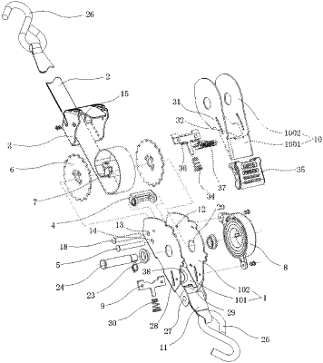
1. A safety control take-up fastening appliance, comprising a base, wherein the base is composed of a base bottom plate and base side plates; the base bottom plate and the base side plates are an integrated structure; the base side plates are perpendicular to the base bottom plate and symmetrically located on both sides of the base bottom plate; the front of the base is provided with a long webbing, a front cover, a movable pendulum block and a guide shaft; the middle of the base is provided with ratchets, a connecting sleeve and a volute spring; the rear of the base is provided with a first pawl, a handle and a short webbing;
the front side of the base side plate is provided with symmetrical riveting holes, pendulum block connecting holes and guide connecting holes; the front cover fits with the front of the base, is sleeved on the front of the base, and is riveted to the base through the riveting holes; the front cover is provided with a first through hole; the movable pendulum block is composed of connecting plates and a pendulum block, and the connecting plates are symmetrically arranged on both sides of the pendulum block; the pendulum block connecting hole is provided with a pendulum block rotating shaft; the pendulum block rotating shaft is in interference clamping with the pendulum block connecting hole, and penetrates the connecting plate; the connecting plate is in clearance fit and rotational connection with the pendulum block rotating shaft; the pendulum block rotates freely with the pendulum block rotating shaft as the central axis; the pendulum block is provided with a second through hole; the guide shaft is placed at the guide connecting hole and is in interference clamping with the guide connecting hole;
the middle of the base side plate is provided with symmetrical ratchet connecting holes; the number of the ratchets is two, and the middle thereof is provided with a clamping hole; the cross section of the connecting sleeve is C-shaped, and both ends thereof are provided with clamping teeth; the two ratchets are clamped and connected to the clamping teeth at both ends of the connecting sleeve through the clamping hole to realize the clamping and fixing of the ratchets and the connecting sleeve; the ratchet connecting hole is fixedly provided with a shaft sleeve, and the rotation of a ratchet rotating shaft and the base side plate is realized through the shaft sleeve; the ratchet rotating shaft penetrates the middle of the ratchet, passes through the connecting sleeve, and is in interference clamping with the connecting sleeve; the connecting sleeve, the ratchet and the ratchet rotating shaft rotate synchronously; the volute spring is arranged on the outer surface of the base side plate; one end of the ratchet rotating shaft is provided with a bayonet, which protrudes from the base side plate and extends into the volute spring; the ratchet rotating shaft is clamped and connected to the volute spring through the bayonet;
one end of the long webbing is sleeved on the ratchet rotating shaft, drawn from the C-shaped opening of the connecting sleeve and wound on the connecting sleeve, and then passes through the guide shaft, the pendulum block rotating shaft, the second through hole and the first through hole in sequence; the other end of the long webbing is connected with end fittings, which are symmetrically located at the rear ends of the base side plates on both sides of the base bottom plate and are fixedly connected by a connecting rod; one end of the short webbing is sleeved on the connecting rod, and the other end thereof is connected to the end fitting;
the rear side of the base side plate is provided with first pawl sliding grooves; the rear side of the base bottom plate is provided with a first limiting plate; the first pawl sliding groove is provided with the first pawl; the first pawl is T-shaped, and both ends thereof are slidably arranged at the first pawl sliding groove, and the lower end thereof is sleeved with a first return spring, which is inserted into the first limiting plate and in slidable fit with the first limiting plate; under the action of the first return spring, the first pawl slides elastically in the direction of the first pawl sliding groove; the first pawl is matched with the ratchets correspondingly;
the handle is composed of a handle bottom plate and handle side plates; the handle bottom plate and the handle side plates are an integrated structure; the handle side plates are perpendicular to the handle bottom plate, and symmetrically located on both sides of the handle bottom plate; the handle side plate is sleeved on the ratchet rotating shaft and is rotatably connected to the ratchet rotating shaft, and freely rotates with the ratchet rotating shaft as the central axis; the handle side plate is provided with symmetrical second pawl sliding grooves; the handle bottom plate is provided with a second limiting plate; the second pawl sliding groove is provided with a second pawl; the second pawl is T-shaped, and both ends thereof are slidably arranged at the second pawl sliding groove, and the lower end thereof is sleeved with a second return spring, which is inserted into the second limiting plate, and in slidable fit with the second limiting plate; under the action of the second return spring, the second pawl slides elastically in the direction of the second pawl sliding groove; the second pawl is matched with the ratchets correspondingly.
|