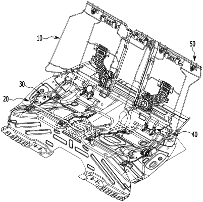
| CPC B60N 2/2209 (2013.01) [B60N 2/015 (2013.01); B60N 2/02246 (2023.08); B60N 2/065 (2013.01); B60N 2/12 (2013.01); B60N 2/02253 (2023.08)] | 12 Claims |

|
1. An apparatus for adjusting a seat of a vehicle, comprising:
a seat back frame;
a cushion frame that is moved forward and backward by a motor driving unit;
a cushion hinge part connecting the seat back frame and the cushion frame, the cushion hinge part being configured to rotate according to the movement of the cushion frame to adjust an angle of the seat back frame; and
a seat back hinge part connecting the seat back frame and a vehicle body, the seat back hinge part being configured to rotate according to the movement of the seat back frame;
wherein the motor driving unit includes:
a motor;
a worm gear connected to a motor shaft and rotated;
a rack gear meshed with the worm gear to convert rotational motion of the worm gear into linear motion;
a leg bracket formed by penetrating a first slot hole on a side surface;
a motor bracket coupled to an outer portion of the motor and covering the worm gear and the rack gear; and
a guide bracket provided above the leg bracket, formed through a second slot hole, and inserted onto a slot pin of the motor bracket to move the motor bracket.
|