| CPC B60G 17/0157 (2013.01) [B60G 13/02 (2013.01); B60G 17/0165 (2013.01); B60G 17/06 (2013.01); B60G 2202/25 (2013.01); B60G 2204/62 (2013.01); B60G 2206/41 (2013.01); B60G 2400/0512 (2013.01); B60G 2400/208 (2013.01); B60G 2400/252 (2013.01); B60G 2400/842 (2013.01); B60G 2500/104 (2013.01); B60G 2600/182 (2013.01); B60G 2600/26 (2013.01); B60G 2800/162 (2013.01)] | 20 Claims |

|
1. A damping system, comprising:
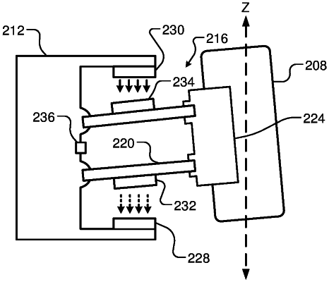
a first magnetic damper pair mounted on or proximate to a suspension system of a vehicle, the first magnetic damper pair comprising
a first magnet mounted on a first surface of a body of the vehicle, and
a second magnet mounted on a first moveable component of the suspension system coupled to a wheel of the vehicle;
at least one sensor mounted on the body of the vehicle or the wheel; and
a damping system control module configured to (i) receive, from the sensor, inputs indicative of a velocity of the wheel relative to the body of the vehicle and a displacement of the wheel relative to the body of the vehicle, (ii) calculate an amount of force to generate between the magnetic damper pair in a direction opposite a direction of movement of the wheel, and (iii) control supply of current to at least one of the first magnet and the second magnet to generate the calculated amount of force.
|