| CPC B60C 11/1612 (2013.01) [B60C 11/032 (2013.01); B60C 2200/14 (2013.01)] | 6 Claims |

|
1. A vehicle tire device comprising:
a tire having an exterior wall and a pair of side walls being attached to each one of a pair of side edges of the exterior wall;
a vehicle rim being sealed against an end edge of each side wall and enclosing a pressurized space between the side walls and the exterior wall of the tire and the vehicle rim, wherein the side walls are airtight to the vehicle rim;
a valve being coupled to the vehicle rim and being in fluid communication with the pressurized space; and
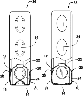
a plurality of depressions being positioned on the exterior wall and being pushed out from a first position to a second position when the pressurized space receives additional air, the first position of each of the depressions having a container space configured for receiving air when driving in muddy soil, wherein the depressions provide buoyancy to the tire in muddy soil, each depression being aligned with the exterior wall of the tire when in its second position wherein the depressions are located on a tire equator of the tire between a first shoulder region of the exterior wall and a second shoulder region of the exterior wall and wherein, in an axial cross section of the tire passing through a maximum axial width of a depression, the maximum axial width of the depression is larger than an axial width of each shoulder region between the side edge of the exterior wall and the depression.
|