| CPC B60C 11/0306 (2013.01) [B60C 11/0309 (2013.01); B60C 11/0332 (2013.01); B60C 11/12 (2013.01); B60C 11/1204 (2013.01); B60C 11/1218 (2013.01); B60C 11/1236 (2013.01); B60C 2011/0346 (2013.01); B60C 2011/0348 (2013.01); B60C 2011/036 (2013.01); B60C 2011/0365 (2013.01); B60C 2011/0369 (2013.01); B60C 2011/0381 (2013.01); B60C 2011/0393 (2013.01); B60C 2011/1209 (2013.01); B60C 2011/1213 (2013.01)] | 16 Claims |

|
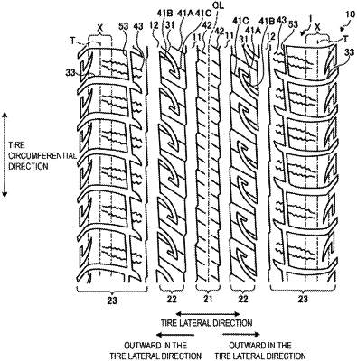
1. A pneumatic tire comprising:
a pair of first main grooves formed on both outer sides, in a tire lateral direction, of a first land portion including a tire equatorial plane, the pair of first main grooves extending in a tire circumferential direction;
a pair of second main grooves lying outside, in the tire lateral direction, of the first main grooves, the pair of second main grooves extending in the tire circumferential direction;
auxiliary grooves formed on each of second land portions between one of the first main grooves and one of the second main grooves, the auxiliary grooves each opening to one of the second main grooves, the auxiliary grooves each terminating in one of the second land portions; and
first sipes inclined in a direction identical to a direction of the auxiliary grooves, the first sipes crossing each of the second land portions, and the first sipes opening at one end to one of the first main grooves and opening at an other end to one of the second main grooves, the first sipes having a width of less than 1.5 mm and extending continuously from the one end opening to the one of the first main grooves to the other end opening to the one of the second main grooves, wherein
the auxiliary grooves are each formed into a shape bending at a bend point, and each include:
a first groove portion extending from an opening end portion at which each of the auxiliary grooves opens to the bend point; and
a second groove portion extending from the bend point to a terminating end portion at which each of the auxiliary grooves terminates;
a groove width of each of the first groove portions gradually reduces from the opening end portion to the bend point;
the second land portions include twice as many sipe openings opening to the second main grooves as auxiliary groove openings opening to the second main grooves;
a number of the sipe openings opening to the second main groove is the same as a number of sipe openings opening to the first main groove;
the second main grooves define third land portions outside, in the tire lateral direction, of the second main grooves,
lug grooves are provided in the third land portions, the lug grooves not communicating with the second main grooves, and
the second main grooves form main groove walls defining the third land portions, wherein the main groove walls defining the third land portions are uninterrupted by sipes and are uninterrupted by grooves.
|