| CPC B41J 2/175 (2013.01) | 21 Claims |

|
1. A liquid ejection head comprising:
a plurality of ejection orifices configured to eject liquid;
a plurality of liquid chambers communicating with the plurality of ejection orifices one-to-one;
an energy generating element that is provided for each of the plurality of liquid chambers and is configured to apply energy to eject the liquid from each of the plurality of ejection orifices;
a plurality of liquid supply paths that communicate with the plurality of liquid chambers and are configured to supply the liquid to the plurality of liquid chambers;
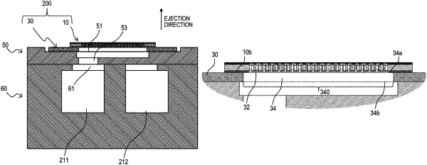
a direction change flow path that communicates with the plurality of liquid supply paths and extends in a direction transverse to the plurality of liquid supply paths; and
a common supply flow path that communicates with the direction change flow path and extends in a direction transverse to the direction change flow path, wherein
the direction change flow path includes a body portion and a grooved flow path having a smaller width than the body portion,
the body portion includes a first wall face provided with at least one opening through which the liquid is supplied to the plurality of liquid supply paths, and
the grooved flow path extends in the first wall face of the body portion along the direction that the body portion extends.
|