| CPC B25J 9/102 (2013.01) [B25J 9/126 (2013.01); B25J 17/00 (2013.01); F16H 57/025 (2013.01); F16H 57/031 (2013.01); F16H 2057/02073 (2013.01)] | 13 Claims |

|
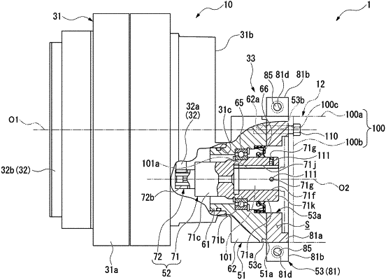
1. A joint comprising:
a joint body having an input gear meshing with a speed reduction mechanism, the joint body receiving an output shaft of a motor detachably coupled to the joint body; and
a motor flange disposed between the speed reduction mechanism and the motor;
an intermediate flange connecting between the motor flange and the motor,
wherein at least one fixing member for fixing the joint body and the output shaft to each other is provided at at least one position in the joint body that overlaps with the intermediate flange as viewed from a radial direction intersecting a rotation axis of the joint body, and
wherein the intermediate flange includes a plurality of split pieces capable of splitting in a circumferential direction around the rotation axis, the intermediate flange is formed as an annulus surrounding the joint body by the plurality of split pieces assembled together.
|