| CPC B25B 27/205 (2013.01) | 18 Claims |
|
1. Adjustable pliers comprising:
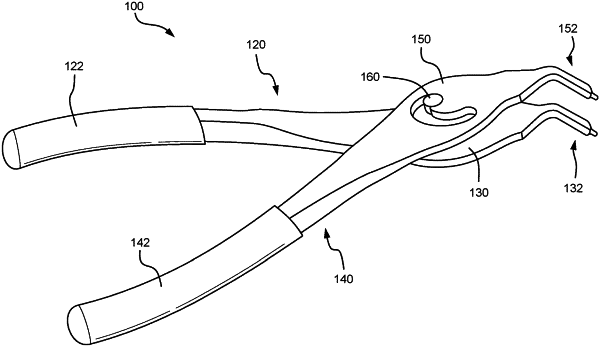
a first plier half including a first handle and a first working tip opposite the first handle;
a second plier half coupled to the first plier half, the second plier half including a second handle, a second working tip opposite the second handle, and a slot extending along a path from a first end of the path to a second end of the path, the path extending in a first direction at the first end of the path and extending in a second direction substantially parallel to the first direction at the second end of the path, wherein the first end of the path and the second end of the path are aligned with a first axis, and wherein the second plier half extends from the second handle to the second working tip in a direction that is substantially aligned with a second axis that is perpendicular to the first axis, and wherein a performance parameter is defined, at least in part, by a relationship between dimensions of the slot and of the first working tip; and
a stud disposed in the slot, the stud being configured to be fixed with respect to the first plier half, wherein when the stud is disposed at the first end of the slot and as the first and second handles are pushed toward each other, the first and second working tips are configured to move away from each other, and wherein when the stud is disposed at the second end of the slot and as the first and second handles are pushed toward each other, the first and second working tips are configured to move toward each other,
wherein the path of the slot extends:
(i) from the first end of the path to a lateral outermost position, the lateral outermost position being spaced from the first end of the path with respect to the first axis by a lateral offset,
(ii) from the lateral outermost position to a most proximal position, the most proximal position being spaced from the first end of the path with respect to the second axis by a longitudinal offset, and
(iii) from the most proximal position to the second end of the path,
wherein the lateral outermost position is disposed on a first curved portion of the path,
wherein the most proximal position is disposed on a second curved portion of the path, and
wherein the performance parameter is defined, at least in part, by a second ratio of (i) the longitudinal offset and (ii) a cross-sectional length of the second working tip along the second axis.
|