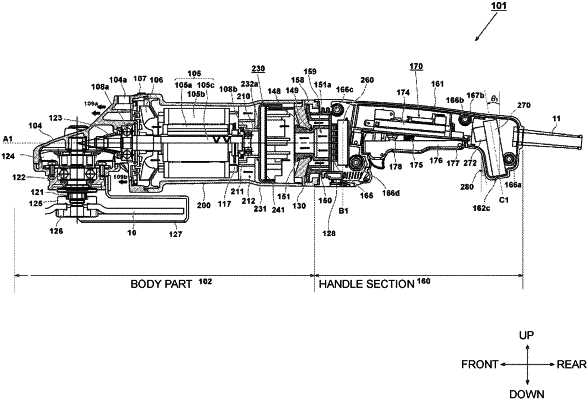
| CPC B24B 47/12 (2013.01) [B24B 23/02 (2013.01)] | 15 Claims |

|
1. An electrically powered tool comprising:
a cylindrical integral motor housing that accommodates and supports a brushless motor having a rotary shaft;
a cooling fan that is rotated by the brushless motor;
a spindle that is rotated by the brushless motor;
a power transmission mechanism configured to transmit a rotational force of the brushless motor to the spindle;
a handle housing connected to one side of the cylindrical integral motor housing and having a grip section;
a gear case which is attached to an other side of the cylindrical integral motor housing in an axial direction and in which the power transmission mechanism is accommodated;
a drive circuit on which a switching element is mounted and which drives the brushless motor;
a first circuit board on which the drive circuit is mounted and which is extending in a direction substantially perpendicular to a rotation axis of the brushless motor;
a second circuit board on which an operation unit configured to control the switching element is mounted; and
a support member which is detachable from the cylindrical integral motor housing,
wherein an air flow window is provided in the handle housing, and when the cooling fan rotates, air is sucked from the air flow window into the handle housing,
wherein the handle housing is configured as a separated body from the motor housing and is divisible, and the handle housing has a diameter-increased section that has a larger diameter than the grip section and is connected to the cylindrical integral motor housing,
the diameter-increased section is positioned between the grip section and the cylindrical integral motor housing, and
the air flow window is provided in the diameter-increased section, and
the second circuit board is accommodated in the diameter-increased section of the handle housing,
the cylindrical integral motor housing comprises a bearing holder supporting an end of the rotary shaft at one side of the rotary shaft and a first circuit board supporting section disposed closer to the one side of the cylindrical integral motor housing than the bearing holder,
the first circuit board is supported by the first circuit board supporting section of the cylindrical integral motor housing and is disposed between the second circuit board supported by the diameter-increased section and the brushless motor, and
wherein the cylindrical integral motor housing is integrally formed without being divisible,
wherein the first circuit board supporting section has a protrusion extending along the axial direction and restricting a rotational movement of the first circuit board,
wherein the support member is restricting an axial movement of the first circuit board supported by the protrusion even when the handle housing is not connected to the cylindrical integral motor housing,
wherein at least a part of the air flow window is disposed between the first circuit board and the second circuit board.
|