| CPC B04B 9/08 (2013.01) [B04B 7/02 (2013.01); B04B 9/12 (2013.01); B04B 2007/025 (2013.01); B04B 2009/085 (2013.01)] | 21 Claims |

|
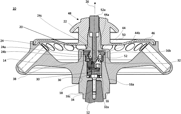
1. Centrifuge (10), comprising:
a drive shaft (12), said drive shaft (12) includes an axis of rotation, a rotor (14) which is mounted on said drive shaft (12) and is axially removable in a removal direction (26),
a quick-acting closure (20) which operates between said rotor (14) and said drive shaft (12) and by means of which said rotor (14) can be fixed relative to said drive shaft (12) in said removal direction (26),
a thrust bearing (44) connected to said drive shaft (12),
a locking bearing (24) connected to said rotor (14),
at least one blocking element (38), which, when activated, fixes said rotor (14) relative to said drive shaft (12) and operates between said locking bearing (24) of said rotor (14) and said thrust bearing (44) of said drive shaft (12), said quick-acting closure (20) has an actuating element (52) and said blocking element (38) is operatively connected to said actuating element (52) such that said quick-acting closure (20) is unlocked by a movement of said actuating element (52) in a direction parallel to the longitudinal axis of said drive shaft (12) and a movement of said blocking element (38) in a direction parallel to longitudinal axis of said drive shaft (12) relative to said locking bearing (24) and/or relative to said thrust bearing (44) and that during locking, a relative movement of said blocking element (38), on the one hand, and of said locking bearing (24) and/or of said thrust bearing (44), on the other hand, toward each other occurs in a direction parallel to longitudinal axis of said drive shaft (12), with said blocking element (38) pivoting about a pivot axis (38b) between a blocking position and an unlocking position,
said blocking element has a cardan shaft (38a), said cardan shaft (38a) rotatable about said pivot axis (38b), said pivot axis is aligned perpendicularly to a straight line parallel to said axis of said drive shaft (12), and
said cardan shaft (38a) engaging a bearing (40).
|