| CPC B01J 35/00 (2013.01) [B01D 53/9481 (2013.01); B01J 19/0013 (2013.01); B01D 2255/9155 (2013.01); B01J 2219/00132 (2013.01); F01N 3/2013 (2013.01); F01N 3/2803 (2013.01); F01N 3/30 (2013.01)] | 8 Claims |

|
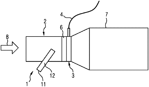
1. A device for the aftertreatment of exhaust gases from an exhaust-gas source, comprising:
a spatially delimited flow path through which flow can pass proceeding from the exhaust-gas source;
a heating catalytic converter which is arranged in the flow path, the heating catalytic converter further comprising:
a catalytically active catalytic converter through which flow may pass, the catalytically active converter further comprising a metallic honeycomb body;
an electrically heatable heating disk arranged downstream in a flow direction from the catalytically active catalytic converter;
a secondary air supply, at least one outlet of the secondary air supply at least partially arranged in at least one cavity formed in the metallic honeycomb body in the region of the heating catalytic converter such that a gas flow referred to as secondary air is fed into the flow path in the region of the heating catalytic converter;
wherein the metallic honeycomb body further comprises corrugated layers and smooth layers downstream of the at least one cavity in the flow direction, wherein the corrugated layers and smooth layers are of perforated form.
|