| CPC A63B 53/0475 (2013.01) [A63B 53/0408 (2020.08); A63B 60/54 (2015.10)] | 10 Claims |

|
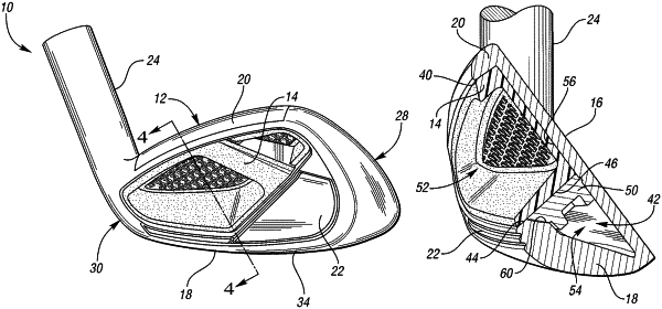
1. A golf club head comprising:
a body comprising a face, and a rear wall, wherein;
the rear wall is opposite the face;
a rear recess is defined where a portion of the rear wall is recessed into the body toward the face;
a first insert comprising a front surface, a rear surface, and a perimeter, wherein;
the first insert is received within the rear recess such that the front surface is in contact with the rear wall;
the rear surface is opposite the front surface;
the perimeter comprises a topline portion, a lower portion, and a toe-side portion;
a portion of the rear surface is recessed into the first insert towards the front surface, thereby defining an open cavity, wherein;
the topline portion, the lower portion, and the toe-side portion of the perimeter circumscribe the open cavity;
the first insert further comprises a reinforcing feature comprising a beam comprising a first end near the topline portion and a second end near the toe-side portion of the perimeter;
wherein the beam extends across the open cavity between the topline portion and the toe-side portion of the perimeter;
the first insert is formed from a first polymeric material;
wherein the first polymeric material has a hardness, measured on the Shore D scale, between 75 D to 90 D;
the body further comprises a sole, wherein the face, the sole, and the rear wall define an undercut volume;
the rear wall defines at an upper edge thereof a threshold surface defining an upper threshold of the undercut volume, and a sloped ledge adjoining the threshold surface and projecting at an obtuse angle from the threshold surface into the undercut volume;
the golf club head further comprises a second insert between a rear surface of the face and the sloped ledge of the rear wall within the undercut volume to thereby define a fluidly sealed empty cavity within the undercut volume; and
wherein the second insert includes a top surface and a sloped surface projecting at an obtuse angle from the top surface, the top surface of the second insert being seated against a bottom perimeter of the first insert, and the sloped surface being seated against the sloped ledge of the rear wall.
|