| CPC A61B 3/14 (2013.01) [A61B 3/0008 (2013.01); A61B 3/12 (2013.01)] | 19 Claims |

|
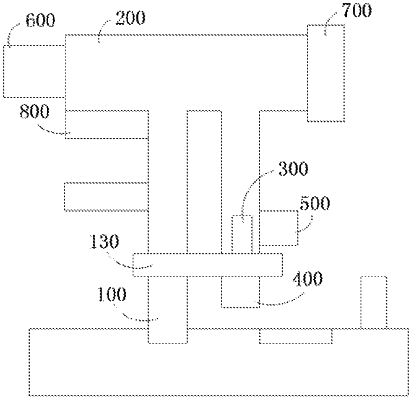
1. A fundus camera, comprising: an illumination module, a main optical assembly, a focusing module, and an image sensing acquisition module; the illumination module comprises a plurality of light sources configured to emit light of different wavelengths, illumination light emitted by the plurality of light sources is conducted to enter an eye of a patient through the main optical assembly, and light reflected by a retina of the patient is conducted to pass through the main optical assembly and the focusing module to enter the image sensing acquisition module;
wherein the illumination light emitted by the illumination module is conducted to form a plurality of arc-shaped illumination areas evenly distributed along a same circumference, and a gap is defined between the adjacent arc-shaped illumination areas.
|