| CPC A61B 18/1815 (2013.01) [A61B 2017/00862 (2013.01); A61B 2017/3456 (2013.01); A61B 17/3496 (2013.01); A61B 2018/00011 (2013.01); A61B 2018/00035 (2013.01); A61B 2018/00178 (2013.01); A61B 2018/00541 (2013.01); A61B 2018/00577 (2013.01); A61B 2018/183 (2013.01); A61B 2018/1869 (2013.01)] | 16 Claims |

|
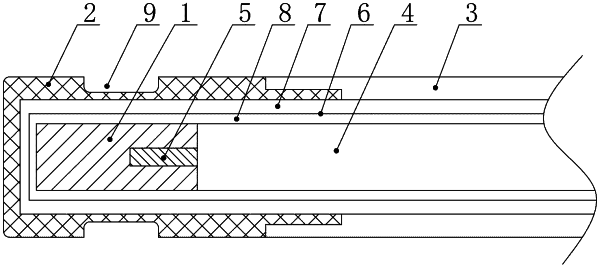
1. A non-puncturing microwave ablation antenna, comprising;
an irradiator located at a front end of the non-puncturing microwave ablation antenna;
an irradiator cover sleeved on the irradiator, wherein a front end of the irradiator cover is blunt;
a needle bar, disposed on a rear end of the irradiator cover; and
a coaxial cable, disposed inside the needle bar in a puncturing manner;
wherein
the coaxial cable comprises an inner conductor and an outer conductor;
the inner conductor is fixed to the irradiator, a medium pipe is sleeved over the irradiator and the coaxial cable, and a first hole is provided as a water inlet/outlet of cooling water in a front end of the medium pipe or/and a sidewall of the front end of the medium pipe;
a first gap is formed between an outer surface of the medium pipe and the irradiator cover and between the outer surface of the medium pipe and the needle bar;
a second gap is formed between an inner surface of the medium pipe and the irradiator and between the inner surface of the medium pipe and the outer conductor of the coaxial cable; and
the first gap serves as a water inlet passage of the cooling water, and the second gap serves as a water return passage of the cooling water; or the second gap serves as the water inlet passage of the cooling water, and the first gap serves as the water return passage of the cooling water.
|