| CPC A61B 18/02 (2013.01) [A61B 2018/00172 (2013.01); A61B 2018/00601 (2013.01); A61B 2018/0063 (2013.01); A61B 2018/0293 (2013.01)] | 20 Claims |

|
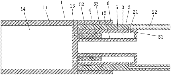
1. A flexible cryoablation needle device resistant to a low temperature and a high pressure, comprising: a cutter head structure and a flexible pipe structure connected to the rear end of the cutter head structure, the cutter head structure is provided with an inner cavity, and the cutter head structure comprises a cutter head front section and a cutter head rear section; the front end of the cutter head rear section is connected to the rear end of the cutter head front section; the cutter head rear section has a smaller outer diameter than the cutter head front section; wherein the flexible cryoablation needle device further comprises a liner pipe, a pressure relief assembly, a pressure relief intermediate cavity and a first extruding pipe; the flexible pipe structure is provided with a pressure relief gap and a flexible pipe vent; the rear end face of the cutter head front section is provided with a cutter head vent; the liner pipe is provided with a liner vent;
the front end of the liner pipe is connected with the rear end face of the cutter head front section; the pressure relief intermediate cavity is formed between the inner side of the liner pipe and the outer side of the cutter head rear section along the radial direction of the cutter head structure; the pressure relief intermediate cavity is formed between the rear end face of the cutter head front section and a fixing part along the axial direction of the cutter head structure; the fixing part is connected between the outer side of the cutter head rear section and the inner side of the liner pipe; the flexible pipe structure is arranged on the outer side of the liner pipe along the radial direction of the cutter head structure; the pressure relief intermediate cavity communicates with the pressure relief gap through the liner vent and the flexible pipe vent; the inner cavity is connected to one side of the cutter head vent; the pressure relief intermediate cavity is connected to the other side of the cutter head vent;
at least a part of the outer wall of the liner pipe is attached to the inner wall of the flexible pipe structure; the outer wall, attached to the flexible pipe structure, of the liner pipe is provided with a concave-convex structure; the first extruding pipe is sleeved outside the flexible pipe structure and is located on the outer side of a part of the concave-convex structure; the concave-convex structure comprises a threaded portion and an annular protrusion portion; and
the pressure relief assembly is arranged in the pressure relief intermediate cavity to close the cutter head vent when a pressure in the inner cavity is lower than a pressure threshold, and control the cutter head vent, the flexible pipe vent and the liner vent to communicate with one another when the pressure in the inner cavity is higher than or equal to the pressure threshold, such that a gas in the cutter head structure is exhausted to relieve the pressure through the cutter head vent, the pressure relief intermediate cavity, the liner vent, the flexible pipe vent and the pressure relief gap in sequence.
|