| CPC A61B 1/0052 (2013.01) [G05G 1/01 (2013.01)] | 20 Claims |

|
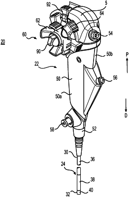
1. A steering system for a medical device, the steering system comprising:
a first drive member having a central longitudinal axis;
a central shaft extending through the first drive member;
a control knob coupled to the first drive member;
a braking knob coupled to the central shaft and including a first protrusion; and
a brake shoe member coupled to the central shaft between the control knob and the braking knob, wherein the first protrusion is positioned within a first channel of the brake shoe member;
wherein the first protrusion is configured to engage the brake shoe member to move a first arm of the brake shoe member radially outward, relative to the central longitudinal axis, towards a wall of the control knob when the braking knob is rotated in a first direction;
wherein the first arm is configured to move away from the wall of the control knob when the braking knob is rotated in a second direction opposite the first direction;
wherein the brake shoe includes:
a central portion including a lumen configured to receive the central shaft;
a first protrusion extending radially-outward, relative to the central longitudinal axis, from the central portion;
a second protrusion extending radially-outward, relative to the central longitudinal axis, from the central portion;
the first arm extending outward from the first protrusion, wherein the first arm is curved towards the central shaft and includes a first expanded end and a first recess;
a second arm extending outward from the second protrusion, wherein the second arm is curved towards the central shaft and includes a second expanded end and a second recess;
a first spring beam extending from the first arm and extending at least partially within the first recess; and
a second spring beam extending from the second arm and extending at least partially within the second recess.
|