| CPC A47H 1/14 (2013.01) | 12 Claims |

|
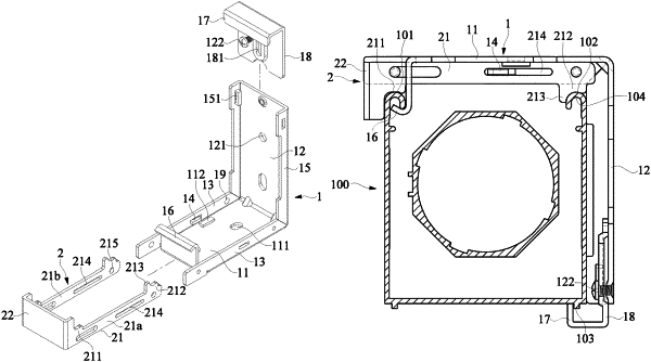
1. A bracket structure is configured to be installed on an upper track of an electric curtain, wherein the upper track has a first hook portion and a second hook portion respectively disposed on two upper sides thereof, the upper track has a convex rib disposed on a bottom portion thereof, and the bracket structure comprises:
a bracket body having a top plate and a rear plate, wherein the rear plate is connected to one end of the top plate, the rear plate extends downward from the end of the top plate, another end of the top plate away from the rear plate extends to form an upper hook portion, the rear plate has a lower hook portion disposed on a lower end thereof, two first side plates are respectively connected with two sides of the top plate, the two first side plates are formed by bending and extending downward from the two sides of the top plate, each of the two first side plates has a guide portion integrally formed thereon, and the guide portion protrudes from the first side plate; and
a locking plate movably disposed on the top plate of the bracket body, wherein the locking plate has a locking plate body and a control part, the locking plate body includes two rod bodies, the two rod bodies are spaced apart from each other, the control part is connected to one end of each of the two rod bodies, the two rod bodies slidably contact the two first side plates of the bracket body, each of the two rod bodies has a guide groove, the guide portion and the guide groove slidably match with each other so as to form a guiding mechanism, one of the two rod bodies has a first pressing abutting portion disposed on a bottom thereof and disposed adjacent to the control part, another one of the two rod bodies has a second pressing abutting portion disposed on a bottom thereof and disposed away from the control part, the second pressing abutting portion extends downward from one side thereof to form a pressing edge, the pressing edge is located at the second pressing abutting portion and disposed adjacent to one side of the first pressing abutting portion, and the pressing edge extends downward by a predetermined length so that two sides of the second pressing abutting portion are asymmetrical;
wherein the upper track is able to be placed between the top plate and the rear plate of the bracket body, so that a bottom of the upper track is placed on the lower hook portion of the bracket body; wherein a bottom protruding rib of the upper track and the lower hook portion of the bracket body are hooked with or abutted against each other, and the first hook portion of the upper track and the upper hook portion of the bracket body are hooked with each other, so that the upper track is temporarily fixed on the bracket structure; wherein, when the locking plate is pushed toward the bracket body, the first pressing abutting portion and the second pressing abutting portion of the locking plate are respectively pressed against the first hook portion and the second hook portion of the upper track so as to fix the upper track on the bracket structure, and the pressing edge is able to be pressed against a front edge of the second hook portion of the upper track.
|