| CPC A47C 17/04 (2013.01) [B60B 33/066 (2013.01)] | 26 Claims |
|
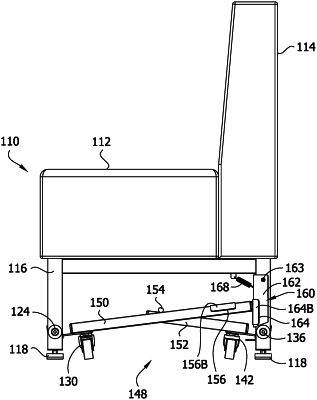
12. A retractable furniture carriage for furniture having support structure disposed to engage and support the furniture on an underlying surface, the retractable furniture carriage comprising:
a first wheel set;
a second wheel set;
a first frame member configured to be mounted on the furniture for pivoting about a first axis, the first wheel set being attached to the first frame member for movement with the first frame member;
a second frame member configured to be mounted on the furniture for pivoting about a second axis parallel to the first axis, the second wheel set being attaching to the second frame member for movement with the second frame member, the first and second frame members being operatively connected for conjoint pivoting from a stowed position in which the first and second wheel sets are spaced from the underlying support surface and the support structure of the furniture engages the underlying surface and supports the furniture on the underlying surface, to a deployed position in which the first and second wheel sets engage the underlying support surface and hold the furniture support structure off of the underlying surface so that the furniture may be moved by rolling on the first and second wheel sets;
an actuation lever operatively connected to the first and second frame members for driving the first and second frame members to move from the stowed position to the deployed position, the actuation lever comprising a first arm connected to the first frame member and extending in a direction transverse to the first axis of the first frame member and a second arm connected to the second frame member and extending in a direction transverse to the second axis of the second frame member;
a keeper configured to pivot about a third axis parallel to the first and second axes between a locked position in which the keeper blocks movement of at least one of the first and second arms to hold the first and second frame members in the deployed position, and an unlocked position in which the keeper does not block movement of at least one of the first and second arms to permit the first and second frame members to move to the stowed position.
|