| CPC A01G 25/023 (2013.01) [A01G 25/06 (2013.01); B05B 1/34 (2013.01)] | 19 Claims |

|
1. An irrigation drip emitter outlet comprising:
an emitter outlet body, distinct from any emitter inlet and any emitter pressure reducing flow path, defining:
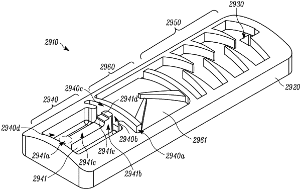
an ingress channel at an upstream opening of the emitter outlet having a first volume and area, and having a first channel without obstructions that is substantially perpendicular to a second channel located downstream of the first channel which causes all fluid flowing through the ingress channel to make a first fluid velocity reducing turn from the first channel to the second channel;
a first opening located off of the second channel that causes at least a portion of the fluid flowing through the ingress channel to make a second fluid velocity reducing turn into a third channel, the first opening forming a constriction between the second channel and the third channel;
a second opening located off of the second channel of the ingress channel further downstream than the first opening that causes at least a portion of the fluid flowing through the ingress channel to make a third fluid velocity reducing turn; and
an outlet bath with a second volume and area that is larger than the first volume and area of the ingress channel so as to cause further pressure and/or velocity reduction of the fluid entering into the outlet bath;
wherein the outlet bath is defined by at least three sidewalls and the outlet bath further includes a rib having first and second ends, with the first end of the rib connected to one of the sidewalls defining at least a portion of the outlet bath and the second end of the rib separating the first opening and second opening off of the ingress channel.
|