| CPC A01C 7/06 (2013.01) [A01C 5/04 (2013.01); A01C 7/18 (2013.01); A01C 7/208 (2013.01)] | 7 Claims |

|
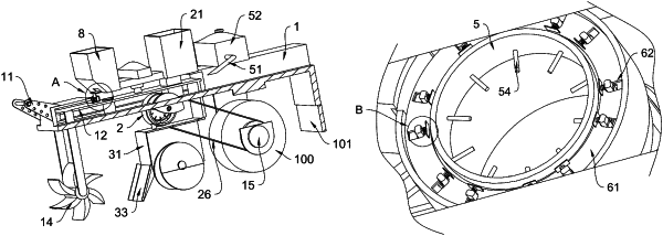
1. A sowing device that change a depth of wheat sowing, comprising:
an external skeleton (1), one side of the external skeleton (1) is fixedly connected with a connection part (11) for articulation with a tractor;
a main board (12) slidably connected to an interior of the external skeleton (1), and a seeding unit (2) is provided under the main board (12);
a support frame (13) fixedly connected to the main board (12), wherein a bottom of the support frame (13) is rotatably connected with a plow blade (14) for slotting land;
a rotary roller (15) provided below the external skeleton (1) and rotationally connected thereto;
wherein the seeding unit (2) comprises a seeding box (21), which is fixedly connected to the external skeleton (1), a bottom of the seeding box (21) is penetrated and extends out of and is fixedly connected with a channel (22), and a bottom of the channel (22) is fixedly connected to a fixed barrel (23), the fixed barrel (23) is rotatably connected with a quantitative barrel (24); the quantitative barrel (24) is provided with quantitative grooves (25) in a circular and equally spaced manner;
an inner wall of the quantitative barrel (24) is provided with a fixed tube (5), which is fixedly connected to an inner wall of the fixed barrel (23); a sponge sleeve (53) is provided between the fixed tube (5) and the quantitative barrel (24), and an inner wall of the sponge sleeve (53) is fixedly connected with multiple liquid guide strips (54) in a circular and equally spaced manner; the liquid guide strips (54) are penetrated and extend out of a side wall of the fixed tube (5) and is flexibly connected thereto;
an inner wall of the quantitative groove (25) is movably connected with an extrusion strip (6), and one end of the quantitative barrel (24) is fixedly connected with a fixed disc (61); the fixed disc (61) is provided with multiple chutes (62), and the extrusion strip (6) is penetrated and extends out of each chute (62) and is slidably connected thereto; the fixed disc (61) is fixedly connected with multiple fixed blocks (63) corresponding to each chute (62), and the fixed blocks (63) are fixedly connected with a support spring (64), the support spring (64) is fixedly connected to the extrusion strip (6).
|