| CPC H04R 1/025 (2013.01) [H04R 2201/021 (2013.01)] | 20 Claims |

|
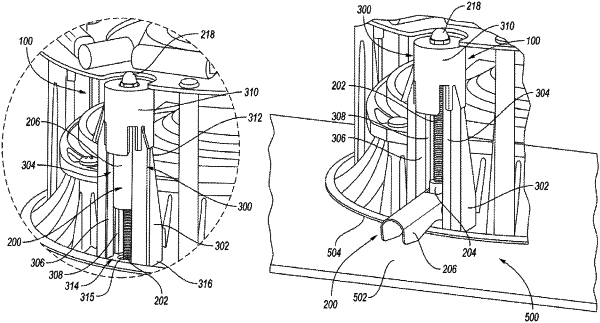
1. A mounting system for a loudspeaker, the mounting system comprising:
a mounting assembly including an elongated screw, a support member received on and movable along the screw, and a mounting arm rotatably connected to the support member, the mounting arm having a resting position and a working position, wherein a bottom end of the support member includes at least one tab extending outwardly therefrom; and
a guide housing which receives the mounting assembly with the screw extending longitudinally therethrough, the guide housing including a wall structure with an open front side and a cap at a top portion of the wall structure, wherein the guide housing includes a bottom surface which limits translation of the support member along the screw via engagement with the tab,
wherein in the resting position the support member is positioned along the screw to be at least partially received within the cap, and in the working position the support member is positioned along the screw to be outside of the cap and the mounting arm is spring-biased away from the screw and extends outwardly through the front side of the wall structure.
|
|
9. A loudspeaker, comprising:
a frame;
at least one mounting system coupled to the frame, the at least one mounting system including
a mounting assembly including an elongated screw, a support member received on and movable along the screw, and a mounting arm rotatably connected to the support member, the mounting arm having a resting position and a working position, a bottom end of the support member including at least one tab extending outwardly therefrom; and
a guide housing which receives the mounting assembly with the screw extending longitudinally therethrough, the guide housing including a wall structure with an open front side and a cap at a top portion of the wall structure, the guide housing including a bottom surface which limits translation of the support member along the screw via engagement with the tab,
wherein in the resting position the support member is positioned along the screw to be at least partially received within the cap, and in the working position the support member is positioned along the screw to be outside of the cap and the mounting arm is spring-biased away from the screw and extends outwardly through the front side of the wall structure.
|
|
18. A method of mounting a loudspeaker to a substrate, the method comprising:
providing at least one mounting system coupled to a frame of the loudspeaker, the at least one mounting system including
a mounting assembly including an elongated screw, a support member received on and movable along the screw, and a mounting arm rotatably connected to the support member, the mounting arm having a resting position and a working position, a bottom end of the support member including at least one tab extending outwardly therefrom; and
a guide housing which receives the mounting assembly with the screw extending longitudinally therethrough, the guide housing including a wall structure with an open front side and a cap at a top portion of the wall structure, the guide housing including a bottom surface which limits translation of the support member along the screw via engagement with the tab;
inserting the loudspeaker in an aperture of the substrate such that the mounting arm is arranged above an interior surface of the substrate; and
placing the mounting arm in the working position by rotating the screw in a first direction to position the support member outside of the cap, such that the mounting arm is spring-biased away from the screw and extends outwardly through the front side of the wall structure and is situated to contact the interior surface of the substrate.
|