| CPC H02M 7/5395 (2013.01) [B60L 15/08 (2013.01); H02M 1/12 (2013.01); H02P 27/08 (2013.01); H02P 29/40 (2016.02); B60L 2210/40 (2013.01)] | 10 Claims |

|
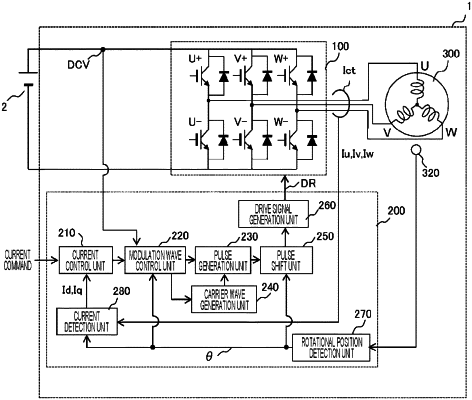
1. An inverter control device, comprising:
a pulse generation unit configured to generate a pulse width modulation (PWM) pulse for controlling an inverter by using a modulation factor based on a voltage command and a pulse period of a predetermined frequency; and
a pulse shift unit configured to correct a phase of the PWM pulse such that the PWM pulse is output at a phase corresponding to a harmonic of a predetermined order of a modulation wave in a near-zero-cross region including a zero-cross point where the modulation wave based on the voltage command changes across 0.
|