| CPC H02K 7/1166 (2013.01) [B60N 2/02246 (2023.08); B60N 2/02253 (2023.08)] | 13 Claims |

|
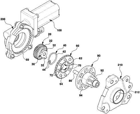
1. A speed reduction device for a motor, comprising:
a transmission gear engaged with an output gear of a motor and disposed in a speed-reducing housing;
a cam including a pair of rotational force transmission protrusions formed to protrude from an outer surface thereof, the cam being integrally mounted on an outer surface of the transmission gear;
a ring gear formed on an outer surface of the housing;
a cycloid inner gear including a through hole formed therein and a plurality of rotational force transmission pins formed thereon, the cycloid inner gear being engaged with the ring gear;
a pair of wedges disposed in close contact with an inner peripheral surface of the through hole so as to respectively contact the pair of rotational force transmission protrusions entering the through hole;
a spring configured to compress the pair of wedges against the inner peripheral surface of the through hole with elastic restoring force; and
an end plate including a plurality of restraining holes formed therein and configured to allow the plurality of rotational force transmission pins to be respectively inserted thereinto so as to enable power transmission.
|