| CPC H02K 11/215 (2016.01) [B23B 45/02 (2013.01); B24B 23/02 (2013.01); B25F 5/008 (2013.01); B26B 15/00 (2013.01); H02K 5/10 (2013.01); H02K 5/15 (2013.01); H02K 5/161 (2013.01); H02K 5/18 (2013.01); H02K 5/207 (2021.01); H02K 7/083 (2013.01); H02K 7/116 (2013.01); H02K 7/145 (2013.01); H02K 9/06 (2013.01); H02K 9/227 (2021.01); H02K 21/16 (2013.01)] | 20 Claims |

|
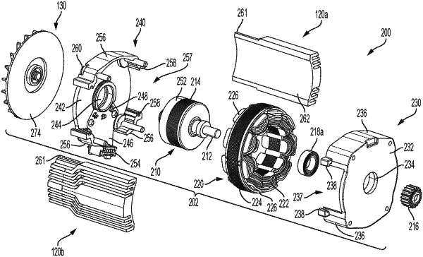
1. A motor comprising:
a motor housing having a main body and an end cap radially oriented relative to the main body;
a stator including a stator main body defining a longitudinal axis securely disposed within the main body of the motor housing, a plurality of stator teeth projecting radially from the stator main body, a plurality of stator windings wound around the plurality of stator teeth, and two winding terminals provided for each of the plurality of stator teeth extending away from the stator main body substantially parallel to the longitudinal axis;
a rotor including a rotor shaft, a rotor core mounted on the shaft, at least one rotor permanent magnet affixed to the rotor core arranged to magnetically interface with the plurality of stator windings, and a bearing mounted on the rotor shaft and housed within a center pocket of the end cap; and
a circuit board oriented along a radial plane perpendicular to the longitudinal axis adjacent the stator, the circuit board including a central through-hole through which the rotor shaft extends, at least one magnetic sensor mounted on a surface of the circuit board around the central through-hole configured to magnetically interface with the rotor, a plurality of peripheral openings arranged to receive the winding terminals of the stator, and a plurality of conductive routings extending from the plurality of peripheral openings to connect the stator windings within each phase of the motor in a series or a parallel configuration and the stator windings within different phases of the motor in a wye or a delta configuration,
wherein the circuit board is secured within the housing in contact with a radial surface of the end cap, and
wherein an inner edge of the circuit board defining the center through-hole includes a first inner portion having a first radius and a second inner portion concentric with the first inner portion and projecting inwardly towards the longitudinal axis and having a second radius that is smaller than the first radius, wherein the at least one magnetic sensor is located along the second inner portion.
|