| CPC H02K 1/276 (2013.01) [H02K 2213/03 (2013.01)] | 16 Claims |

|
1. A rotor, comprising:
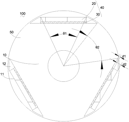
a rotor core provided with magnetic steel slots, the magnetic steel slots being arranged at intervals on an axial end face of the rotor core in a circumferential direction of the rotor core;
at least two first permanent magnets and at least two second permanent magnets, wherein: a coercivity of each first permanent magnet is different from a coercivity of each second permanent magnet; the at least two first permanent magnets and the at least two second permanent magnets are arranged in an axial direction in the magnetic steel slots of the rotor core; one of the first permanent magnets and one of the second permanent magnets are arranged in series in a radial direction of the rotor core in one slot to form a permanent magnet pole;
a circumferential part of the rotor core located between every two adjacent permanent magnet poles forms a consequent pole, and the permanent magnet pole form a magnetic circuit passing through the consequent pole;
the coercivity of each first permanent magnet is less than the coercivity of each second permanent magnet, and in each of magnetic steel slots, the first permanent magnet is located on one side farther away from a center of the rotor core in the radial direction of the rotor core than is a corresponding second permanent magnets;
a width of each of the first permanent magnets is set to be greater than a width of each of the second permanent magnets; and
dimensions of each of the first permanent magnets and dimensions of each of the second permanent magnets satisfy
50 A/m<(H1×d1+H2×d2)/(d1+d2)<400 A/m;
wherein d1 denotes the width of each of the second permanent magnets, d2 denotes the width of each of the first permanent magnets, H1 denotes the coercivity of each of the second permanent magnets, and H2 denotes the coercivity of each of the first permanent magnet.
|