| CPC H01L 25/18 (2013.01) [H01L 23/5329 (2013.01); H01L 23/5383 (2013.01); H01L 23/5386 (2013.01); H01L 23/66 (2013.01); H01L 24/17 (2013.01); H01L 2223/6627 (2013.01); H01L 2224/0237 (2013.01)] | 17 Claims |
|
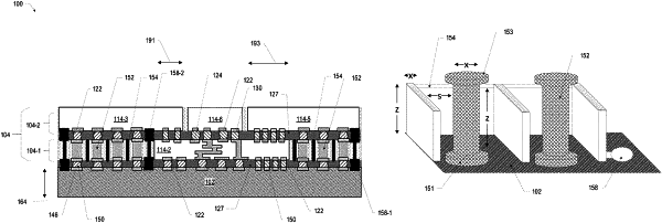
1. A microelectronic assembly, comprising:
a package substrate having a first surface and an opposing second surface;
a first die having a first surface and an opposing second surface, wherein the first die is embedded in a first dielectric layer, wherein the first surface of the first die is coupled to the second surface of the package substrate, and wherein the first dielectric layer is between a second dielectric layer and the second surface of the package substrate;
a second die having a first surface and an opposing second surface, wherein the second die is embedded in the second dielectric layer, wherein the first surface of the second die is coupled to the second surface of the package substrate by a conductive pillar; and
a conductive, radio frequency shield structure, wherein the shield structure surrounds the conductive pillar.
|