| CPC H01H 13/14 (2013.01) [H01H 13/20 (2013.01)] | 9 Claims |

|
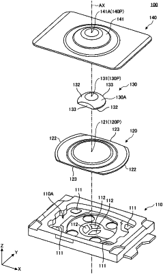
1. A push switch comprising:
a case including a housing space having an upper opening and including fixed contacts disposed on a bottom of the housing space;
a movable contact member disposed in the housing space configured to deform in response to receiving pressure applied from above, and contacting the fixed contacts upon deforming in response to the received pressure, said movable contact member having a dome shape and being made of a single metal plate; and
a pushing member disposed on a top part of the dome shape of the movable contact member at a center of the movable contact member in plan view and configured to transmit the received pressure to the movable contact member,
wherein the movable contact member includes a pair of first linear edges that are arranged so as to be line-symmetrical and face each other, and a pair of first curved edges that are arranged so as to be line-symmetrical and face each other so as to define an entire periphery of the movable contact member,
wherein the pushing member includes a pair of second linear edges that are arranged to be line-symmetrical and parallel to the pair of the first linear edges, said pushing member further including a plurality of projecting pressing portions disposed on a bottom surface of the pushing member facing the movable contact member, and
wherein the plurality of projecting pressing portions are disposed on the bottom surface at positions not overlapping a straight line that passes through the center of the movable contact member and intersecting each of the pair of first linear edges, said plurality of projecting pressing portions being arranged so as to be symmetrical relative to the center of the movable contact member in plan view.
|