| CPC H01G 4/015 (2013.01) [H01G 2/14 (2013.01); H01G 4/224 (2013.01)] | 4 Claims |

|
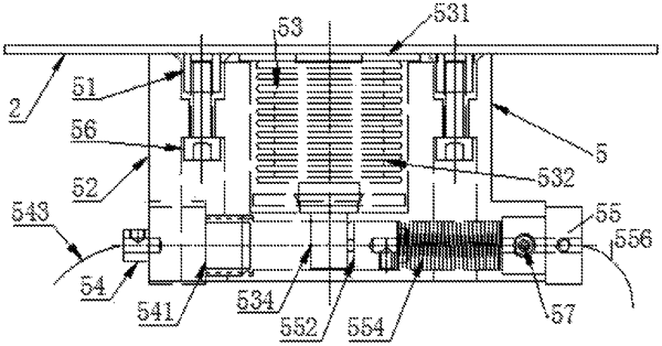
1. A pressure protector for a high-voltage self-healing capacitor, the pressure protector being installed in the high-voltage self-healing capacitor, wherein the pressure protector comprises:
fixed studs,
a protector shell,
a movable bolt assembly,
a fixed electrode assembly,
a movable electrode assembly,
first fixed bolts and a limiting bolt;
wherein the protector shell is L-shaped,
a circular step groove with a depth of 2 mm and a cylindrical cavity with a depth of 40 mm being sequentially formed in the middle of an upper portion of the protector shell,
notches with a depth of 2 mm being formed in the circular step groove and the outer surface of the protector shell,
four longitudinal cylindrical through holes being formed in the periphery of the protector shell,
a U-shaped groove being formed in bottom of the protector shell and connected with a transverse cylindrical through hole,
a square hole being formed between the cylindrical cavity and the transverse cylindrical through hole, and
the protector shell being made of polycarbonate and being formed into a whole through die stamping;
the movable bolt assembly including a circular ring, a spring tube, a stainless steel gasket, a bolt body and an epoxy gasket;
the fixed electrode assembly including a fixed electrode body, a second fixed bolt and a fixed lead-out wire;
the movable electrode assembly having a movable electrode body, a movable electrode, an inner connecting wire, a spring, third fixed bolts and a movable lead-out wire;
one end of each of the fixed studs being welded with a cover plate, and another end of each of the fixed studs being arranged in a corresponding one of the longitudinal cylindrical through holes of the protector shell and fixed through a corresponding one of the first fixed bolts;
the circular ring of the movable bolt assembly and the cover plate being welded together and clamped in the circular step groove,
the spring tube, the stainless steel gasket and the epoxy gasket of the movable bolt assembly all being arranged in the cylindrical cavity of the protector shell, and the bolt body being inserted into the transverse cylindrical through hole of the protector shell through the square hole;
the fixed lead-out wire of the fixed electrode assembly being connected with wiring terminals of the capacitor,
one end of the fixed electrode body being placed in the U-shaped groove of the protector shell, and another end of the fixed electrode body being connected with one end of the transverse cylindrical through hole in a threaded fit mode; and
the movable electrode, the inner connecting wire and the spring of the movable electrode assembly being placed in the transverse cylindrical through hole,
the movable electrode body part of the movable electrode assembly being placed in the transverse cylindrical through hole and positioned through the limiting bolt, and
the movable lead-out wire of the movable electrode assembly being connected with the wiring terminals of the capacitor.
|