| CPC G01M 17/007 (2013.01) [B64F 5/60 (2017.01)] | 9 Claims |

|
1. A method to test an unmanned aerial vehicle (UAV) using a test bench, said method comprising:
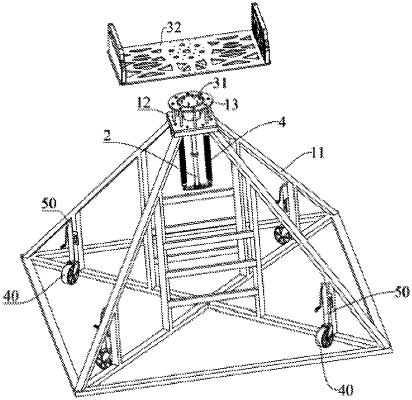
providing a support component (1);
providing a universal rotating component (2), which slides on the support component (1) along a Z direction, and a first end of the universal rotating component (2) can rotate in a universal manner relative to a second end of the universal rotating component (2);
providing a fixing component (3), which is connected to the first end of the universal rotating component (2), and the fixing component (3) is configured to fix the UAV;
providing a return component (4), wherein a first end of the return component is connected to the support component (1), and a second end of the return component is connected to the second end of the universal rotating component (2); wherein the return component (4) is configured to drive the universal rotating component (2) and the fixing component (3) to reset; and
wherein the support component (1) comprises a support frame (11), a first support plate (12), a second support plate (13) and a plurality of support columns (14);
wherein the first support plate (12) is fixedly connected to a first end of the support frame (11), and the second support plate (13) is connected with the first support plate (12) through the plurality of support columns (14);
wherein the first support plate (12) has a first through hole;
wherein the universal rotating component (2) is configured to slide through the first through hole;
wherein the first end of the return component (4) is connected to the first support plate (12), and the second support plate (13) is configured to support the fixing component (3).
|