| CPC G01B 11/165 (2013.01) [G01B 11/167 (2013.01); G02B 5/1871 (2013.01); G02B 27/425 (2013.01); G02B 27/50 (2013.01)] | 24 Claims |

|
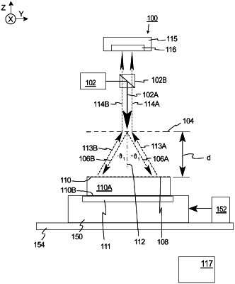
1. A measurement system for use in measurements of in-plane distortions of a workpiece diffraction grating that is configured to diffract light in reflection, the measurement system comprising:
an optical detector;
a reference diffraction grating that is spaced apart from the workpiece diffraction grating, the reference diffraction grating being configured to diffract light in transmission; and
a light source that directs a measurement beam at the reference diffraction grating;
wherein the measurement beam directed at the reference diffraction grating is (i) diffracted and transmitted through the reference grating and directed at the workpiece diffraction grating, (ii) subsequently diffracted and reflected off of the workpiece diffraction grating and directed at the reference diffraction grating, and (iii) then subsequently transmitted through the reference grating as diffracted output beams and directed at the optical detector; and
wherein the optical detector acquires the output beams to generate an interference image having a spatial light distribution with a phase that is used to determine in plane distortions of the workpiece diffraction grating.
|