| CPC F21V 21/002 (2013.01) [F21V 21/005 (2013.01)] | 17 Claims |

|
1. A luminaire system (1) comprising:
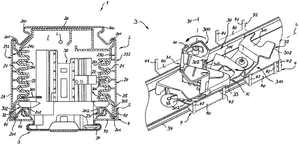
a support rail (2), which comprises an elongated support profile (20) with a longitudinal extension (L) delimiting an inner space (I) as well as a current conducting profile (21) with wires (22) arranged extending longitudinally in the inner space (I) for supplying power and/or transmitting digital control commands, wherein the support profile (20) is formed by at least two side walls (24, 25) a rear wall (26) connecting the side walls (24, 25), each side wall having a substantially exposed outer surface and a locking portion disposed inward from the substantially exposed outer surface, the side walls delimiting a longitudinal opening (23) in a laterally opposed manner and
a component (3) having a coupling element (30), which can be inserted into the inner space (I) of the support profile (20) via the opening (23) and can be actuated therein, such that simultaneously a contacting element (31) of the coupling element (30) electrically contacts the wires (22) of the current conducting profile (21) for the electrical connection of the component (3) and a locking element (32) of the coupling element (30) interacts with the locking portions (202) of the side walls (24, 25) of the support profile (20) provided on both sides of the opening (23) for mechanically coupling the component (3) to the support profile (20),
wherein the component (3) further comprises a blocking element (4) that is substantially U-shaped with blocking portions (41, 42) and a base carrier (40) away from which the blocking portions (41, 42) extend, the blocking portions being arranged adjacent to each of the side walls (24, 25) at outer sides (242, 252) facing away from the inner space (I) when the coupling element (30) is inserted, such that the blocking portions (41, 42) prevent a release of the mechanical coupling by means of migration of the respective side wall (24, 25) away from the inner space (I), when the coupling element (30) is actuated.
|