| CPC F16K 37/0058 (2013.01) [F16K 31/607 (2013.01); F16K 35/025 (2013.01); F16K 1/02 (2013.01)] | 4 Claims |

|
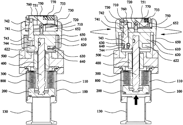
1. An angle valve with a locking check function, comprising:
a main body portion in which an internal movement path, an inlet, and an outlet are formed;
an opening and closing blade provided on the internal movement path to open and close the outlet;
a shaft portion coupled to an upper portion of the opening and closing blade and having a thread formed on an outer side surface;
an upper flange portion that is coupled to an upper portion of the main body portion, has a first seating space formed on an inner side, and has a first through hole formed as a perforation in a lower portion of the first seating space and through which the shaft portion passes;
a lifting guide block fixed to an interior of the upper flange portion;
a handle portion surrounding the upper flange portion and coupled to the shaft portion to move the shaft portion in up and down directions according to a rotation direction of the handle portion and to ascend or descend the opening and closing blade; and
an opening and closing display guide portion that is coupled to an upper side of the handle portion and, when the handle portion rotates counterclockwise such that the opening and closing blade closes the outlet, the opening and closing display guide portion ascends to display “CLOSE,”
wherein the handle portion comprises:
a locking pin fixture that is seated in the first seating space, has a second seating space formed on an inner side, has a second through hole formed as a perforation in a lower portion of the second seating space and through which the shaft portion passes, and has a locking hole formed as a perforation on an outer peripheral surface;
a rotating body that is seated in the second seating space, a coupling groove recessed in a lower portion of the rotating body and coupled to the shaft portion, a locking pin moving space is recessed in an inner direction around an outer peripheral surface of a lower side of the rotating body, and a coupling protrusion is formed in a vertical direction in the locking pin moving space;
a locking pin that is located within the locking pin moving space and is formed in a “C”-shape in which a hinge hole is formed as a perforation and is coupled to the coupling protrusion to form a hinge, and a locking protrusion is formed to protrude and be caught by the locking hole according to a rotation direction of the rotating body on an outer side and limit a rotational movement of the rotating body;
a first spring wound around the coupling protrusion, one side of the first spring is in contact with an inner surface of the second seating space, and the other side of the first spring is coupled to the locking pin and pushes the locking protrusion outward through elastic force; and
a gripping portion with a split plate formed inside to form a third seating space where the opening and closing display guide portion is seated in an upper portion of the gripping portion and to form a fourth seating space surrounding the locking pin fixture and the upper flange portion in a lower portion of the gripping portion.
|