| CPC F04D 25/082 (2013.01) [F04D 17/10 (2013.01); F04D 29/0513 (2013.01); F04D 29/056 (2013.01); F04D 29/5806 (2013.01)] | 16 Claims |

|
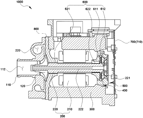
1. An air compressor for a vehicle, the air compressor comprising:
an impeller compressing introduced air to generate compressed air;
a driving unit including a stator, a rotor coupled to the impeller, and a rotor disk integrally formed at a rear of the rotor to drive the impeller;
a driving housing in which the driving unit is provided;
an impeller housing coupled to a front of the driving housing and having the impeller therein;
a first cover coupled to a rear of the driving housing and supporting a front of the rotor disk; and
a second cover coupled to the first cover to support the other side of the rotor disk,
wherein the air compressor for a vehicle includes a bearing unit including a first airfoil bearing and a second airfoil bearing respectively provided at a front and rear of the rotor disk,
wherein the air compressor for a vehicle includes a cooling flow path for cooling the bearing unit and the rotor by introducing the compressed air discharged from the impeller into the bearing unit,
wherein the cooling flow path includes:
a first cooling flow path in which a portion of the air compressed by the impeller performs cooling, while moving from the front to the rear along an outer side of the rotor to perform cooling; and
a second cooling flow path in which the air moved from the first cooling flow path performs cooling, while moving toward the impeller along a hollow shaft portion in which a center of the rotor is axially hollow, and
wherein the second cover includes a hollow portion in which a central predetermined region is hollow so that the first cooling flow path and the second cooling flow path communicate with each other,
wherein the cooling flow path includes a bypass flow path through which the compressed air bypasses at least a portion of the bearing unit,
wherein the bypass flow path is formed by a first hollow hole penetrating through the first cover,
wherein the bypass flow path is formed by a second hollow hole penetrating through the second cover, and
wherein the first hollow hole forms a space that air inside the driving housing bypasses, without passing through the rear journal bearing, and the second hollow hole forms a space that air moved through the first hollow hole or air passing through the rear journal bearing and the first airfoil bearing of the first cooling flow path bypasses, without passing through the second airfoil bearing.
|