| CPC F03G 3/094 (2021.08) | 19 Claims |

|
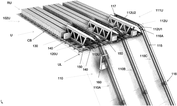
1. An energy storage and delivery system, comprising:
one or more cableways extending between a lower end and an upper end, the upper end being at a higher elevation than the lower end, each cableway comprising:
an upper block storage at the upper end comprising a row defined by a pair of rails configured to support a plurality of blocks thereon,
an upper support frame aligned with a distal end of the row of the upper block storage,
a first trolley movably coupled to said pair of rails of the row of the upper block storage, the first trolley configured to travel below the plurality of blocks disposed on the pair of rails of the row of the upper block storage, the first trolley operable to lift one block of the plurality of blocks above the pair of rails of the row of the upper block storage and to move said block horizontally along the row of the upper block storage to or from an upper landing zone at the distal end of the row of the upper block storage,
a lower block storage at the lower end comprising a row defined by a pair of rails configured to support a plurality of blocks thereon,
a lower support frame aligned with a distal end of the row of the lower block storage,
a second trolley movably coupled to said pair of rails of the row of the lower block storage, the second trolley configured to travel below the plurality of blocks disposed on the pair of rails of the row of the lower block storage, the second trolley operable to lift one block of the plurality of blocks above the pair of rails of the row of the lower block storage, and to move said block horizontally along the row of the lower block storage to or from a lower landing zone at the distal end of the row of the lower block storage,
one or more cables extending between and coupled to the upper support frame and the lower support frame,
a cage configured to travel along the one or more cables between and over at least a portion of the upper support frame and the lower support frame, the cage fixedly coupled to one or more traction cables that loop around a first traction motor wheel operatively coupled to the upper support frame and around a second traction motor wheel operatively coupled to the lower support frame,
a first rotator platform pivotally coupled to a distal end of the pair of rails of the row of the upper block storage, the first rotator platform defining one or more cutouts or gaps configured to allow the first trolley to be positioned under the first rotator platform while the first trolley supports the one block of the plurality of blocks spaced above the pair of rails of the row of the upper block storage, and
a motor-generator operatively coupled to one or both of the first traction motor wheel and the second traction motor wheel, the motor-generator operable to power one or both of the first traction motor wheel and the second traction motor wheel to move the cage from the lower end to the upper end, the motor-generator configured to generate electricity from a rotation of one or both of the first traction motor wheel and the second traction motor wheel when the cage moves from the upper end to the lower end at least partially under a force of gravity,
wherein the cage is operable to move the plurality of blocks one-by-one from the lower end to the upper end to store an amount of electrical energy corresponding to a potential energy amount of said blocks, and wherein the cage is operable to move the plurality of blocks from the upper end to the lower end at least partially under the force of gravity to generate an amount of electricity, the cage moving each of the plurality of blocks between the upper end and the lower end along a same vertical distance.
|