| CPC E21B 31/03 (2013.01) [E21B 7/04 (2013.01); E21B 21/103 (2013.01); E21B 34/14 (2013.01); E21B 37/00 (2013.01); E21B 41/0078 (2013.01)] | 12 Claims |

|
1. A jet flow adjustment method, comprising steps of:
defining a diversion ratio (p) of a jet nozzle (2) by a ground control system according to a cleaning requirement of a cuttings bed;
sending the diversion ratio (p) of the jet nozzle (2) to a control unit of a downhole rotary steerable system;
determining an opening area (s) of the jet nozzle (2) by the control unit of the downhole rotary steerable system according to the diversion ratio (p) of the jet nozzle (2) and an equivalent channel area (S) of a drilling tool, wherein a calculation formula is:
s=p*S/(1−p);
controlling an adjustable bypass valve (3) by the control unit of the downhole rotary steerable system according to the opening area (s) of the jet nozzle (2), so as to control an overlapping area between sector holes (9) of a rotor end (7) and a stator end (8), thereby opening the jet nozzle (2); and
waiting for the ground control system to close the jet nozzle (2);
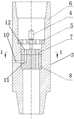
wherein the adjustable bypass valve (3) comprises a drive motor (4), the rotor end (7) and the stator end (8), wherein an output shaft of the drive motor (4) is connected to the rotor end (7); the sector holes (9) are drilled on both the rotor end (7) and the stator end (8); the drive motor (4) drives the rotor end (7) to rotate relative to the stator end (8), thereby changing the overlapping area between the sector holes (9) of the rotor end (7) and the stator end (8) to open and close the jet nozzle (2).
|