| CPC E01F 7/045 (2013.01) | 8 Claims |

|
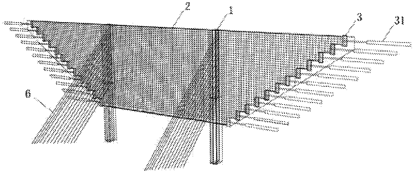
1. A barrier structure for bearing a high-energy impact, comprising: a supporting pile array arranged between two opposite mountain slope surfaces; wherein the supporting pile array is arranged in a straight line and comprises two or more supporting piles, and a preset distance between each two adjacent supporting piles of the two or more supporting piles is preset;
the two or more supporting piles are fixed at a lower part of a mountain, a barrier net is connected to the two or more supporting piles, the barrier net passes through the supporting pile array and extends to the two opposite mountain slope surfaces, and the barrier net is fixed on the two opposite mountain slope surfaces;
each of the two opposite mountain slope surfaces is provided with pull plates thereon, one side of each of the pull plates is fixed to a corresponding mountain slope surface of the two opposite mountain slope surfaces through reverse prestressed anchor cables, and the other side of the pull plate is connected to the barrier net for fixing the barrier net;
a height of the barrier net is not less than 6 meters (m), a yield elongation rate of a material of the barrier net is not less than 0.2%, and a fracture elongation rate of the material of the barrier net is not less than 20%;
the barrier net has a grid-like structure comprising transverse steel strands and longitudinal steel strands, the transverse steel strands are connected to the pull plates, a spacing between each two adjacent transverse steel strands of the transverse steel strands is not greater than 0.3 m;
the spacing between each two adjacent transverse steel strands satisfies a following relationship:
h≤n/(3√V+1)
where h represents the spacing between each two adjacent transverse steel strands, n represents the number of the transverse steel strands, and V represents a volume of a rockfall;
the number of the transverse steel strands satisfies the following relationships:
MgH≤n(W1+W2)
W1=F2×L×Δ1−F1×L×Δ0
W2=F2×L×(Δ2−Δ1)
where M represents a mass of the rockfall, H represents a height difference from a position where the rockfall falls to a position of the barrier net where the rockfall collides with the barrier net, W1 represents a work done during an elastic stage of a single transverse steel strand of the transverse steel strands, W2 represents a work done during a plastic stage of the single transverse steel strand, F1 represents a preload applied to the single transverse steel strand, F2 represents a yield critical force of the single transverse steel strand, L represents a length of the single transverse steel strand, Δ0 represents a preload stretch rate of the single transverse steel strand, Δ1 represents a yield elongation of the single transverse steel strand, and Δ2 represents a plastic deformation elongation rate of the single transverse steel strand.
|