| CPC B60G 7/001 (2013.01) [B60G 3/22 (2013.01)] | 16 Claims |

|
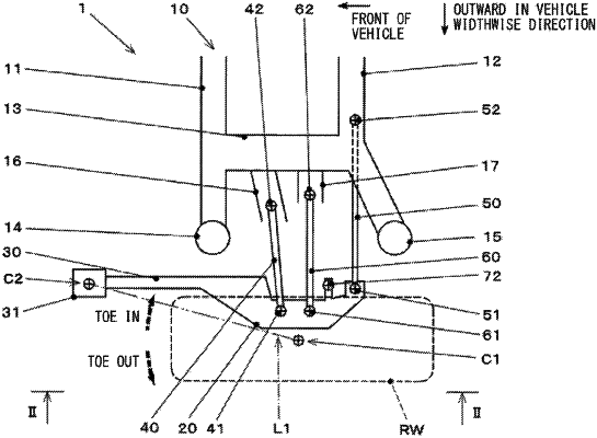
1. A suspension comprising:
a housing to which a hub bearing is attached, the hub bearing rotatably supporting a rear wheel of a vehicle;
links each including both ends spaced apart in a vehicle widthwise direction, the links each coupling the housing to a vehicle body of the vehicle;
a radius arm unitized with the housing and protruding from the housing toward front of the vehicle; and
a radius arm bush provided on a front end of the radius arm, the radius arm bush coupling the radius arm to the vehicle body, with an elastic body in between, the radius arm bush being disposed vehicle-widthwise inwardly of a wheel center contact point of the rear wheel,
wherein the radius arm bush comprises:
an inner cylinder including both ends spaced apart in the vehicle widthwise direction, the inner cylinder being fixed to one of the vehicle body and the radius arm;
an outer cylinder in which the inner cylinder is inserted, the outer cylinder being fixed to another of the vehicle body and the radius arm;
the elastic body provided between an outer circumferential surface of the inner cylinder and an inner circumferential surface of the outer cylinder;
an upper deformation resistant member including a harder material than the elastic body and provided between the outer circumferential surface of the inner cylinder and the inner circumferential surface of the outer cylinder, the upper deformation resistant member being provided in an upper region upward of a first straight line when viewed from a first direction parallel to a central axis of the inner cylinder, the first straight line passing through, when viewed from the first direction, the central axis of the inner cylinder and a wheel center contact point of the rear wheel; and
a lower deformation resistant member including a harder material than the elastic body and provided between the outer circumferential surface of the inner cylinder and the inner circumferential surface of the outer cylinder, the lower deformation resistant member being provided in a lower region downward of the first straight line when viewed from the first direction,
wherein when viewed from a second direction orthogonal to the central axis of the inner cylinder, a center of the upper deformation resistant member in the first direction is located vehicle-widthwise inwardly from a center of the lower deformation resistant member in the first direction,
wherein when viewed from the second direction, a vehicle-widthwise outward end of the upper deformation resistant member in the first direction is located vehicle-widthwise inwardly from a vehicle-widthwise outward end of the elastic body in the first direction,
wherein when viewed from the second direction, a vehicle-widthwise inward end of the lower deformation resistant member in the first direction is located vehicle-widthwise outwardly from a vehicle-widthwise inward end of the elastic body in the first direction, and
wherein the radius arm bush has higher rigidity with respect to turn of the radius arm with respect to the vehicle body in a direction in which an underside of the radius arm is displaced vehicle-widthwise outwardly from an upside of the radius arm, than rigidity with respect to turn of the radius arm with respect to the vehicle body in a direction in which the underside of the radius arm is displaced vehicle-widthwise inwardly from the upside of the radius arm.
|