| CPC B41J 2/15 (2013.01) [B41J 2/14233 (2013.01); B41J 2002/14306 (2013.01)] | 19 Claims |

|
1. A liquid ejecting head comprising:
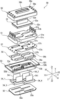
a plurality of head chips having a nozzle surface provided with a nozzle configured to eject a liquid;
a thermally conductive holder holding the plurality of head chips;
a thermally conductive flow path structure provided with a flow path of a liquid supplied to the plurality of head chips; and
a planar heater disposed between the holder and the flow path structure, the planar heater includes a first major planar surface that faces the thermally conductive holder, an opposite second major planar surface that faces the thermally conductive flow path structure, and a side surface that connects the first and second major planar surfaces to each other, each of the first and second major planar surfaces being arranged in parallel with the nozzle surface such that the heater overlaps the plurality of head chips in a plan view, the side surface being arranged orthogonal to the nozzle surface and each of the first and second major planar surfaces, and a surface area of the side surface being less than that of each of the first and second major planar surfaces,
wherein the flow path structure overlaps the plurality of head chips in the plan view.
|