| CPC B23K 11/16 (2013.01) [B21J 15/00 (2013.01); B23K 11/002 (2013.01); B23K 11/0066 (2013.01); B23K 20/02 (2013.01); B23K 2101/006 (2018.08)] | 23 Claims |

|
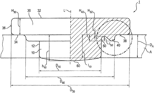
1. A welding auxiliary joining part with which a welding connection is establishable between a first component of poorly weldable material and a second component of weldable material, which comprises the following features:
a. a punch shaft which is punchingly pressable into the first component without rotation, which extends along a longitudinal axis of the welding auxiliary joining part and which has an element head at a first axial end and a welding contact zone projecting in the axial direction from the punch shaft at a second axial end,
b. the element head extends radially beyond the punch shaft and comprises a head upper side facing away from the shaft and a head underside facing towards the shaft, which are connected to one another by means of a circumferential face which radially delimits the element head, and in which
c. the head underside comprises one or more rings protruding from the head underside axially in the direction of the punch shaft, wherein the one or more rings include only:
c1. one clamping ring,
c2. one clamping ring and one stamping ring,
c3. two clamping rings, or
c4. two clamping rings and one stamping ring, wherein
d. in each case the radially outermost ring is surrounded at the side facing away from the punch shaft by a radially extending outer ring face at the head underside, and
e. the clamping ring extends around the punch shaft in a closed manner and projects axially in the direction of the punch shaft, wherein the axial cross-sectional shape of the clamping ring is formed by a radially inner ring side and a radially outer ring side and
e1. the radially inner ring side of which is arranged at a first radial distance from the punch shaft,
e2. the radially outer ring side of which is arranged at a side facing away from the punch shaft radially spaced from the circumferential face of the element head, and
e3. the inner ring side encloses with the punch shaft an inclination angle α in the range of 10°<α<70°, and
e4. the at least one first clamping ring has a triangular cross-sectional shape which tapers in the axial direction of the punch shaft and has a rounded axial end so that the at least one first clamping ring clamps the punch shaft by a correspondingly diverted material flow and does not hinder the penetration of the welding auxiliary joining part into the first component at the same time, and
g. the welding contact zone at the second axial end is adapted to project beyond a side of the first component facing away from the element head, and the head underside is adapted to abut at a side of the first component facing the element head so that the head underside comprising the one or more rings is axially spaced from the second axial end.
|