| CPC B23D 47/12 (2013.01) [B23D 47/02 (2013.01); B23D 59/003 (2013.01); B27B 5/30 (2013.01); B27B 5/32 (2013.01); B27B 9/02 (2013.01); B27B 9/04 (2013.01); B27G 19/04 (2013.01)] | 17 Claims |

|
1. A circular saw, comprising:
a motor including a motor shaft configured to rotate about a shaft rotational axis;
an arbor configured to operatively attach a circular saw blade to the circular saw and to receive a torque from the motor when the motor shaft rotates about the shaft rotational axis;
a switch configured to selectively apply an electric current to the motor;
a switch lever configured to be selectively actuated, by a user of the circular saw by application of an actuation force, to actuate the switch and thereby to apply the electric current to the motor; and
a lock assembly that includes a switch lock, wherein the switch lock:
(i) defines a switch-locked configuration in which the switch lock resists actuation of the switch lever by the user of the circular saw;
(ii) defines a switch-unlocked configuration in which the switch lever is free to be actuated by the user of the circular saw to actuate the switch; and
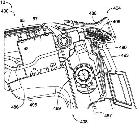
(iii) includes an off lock lever configured to be selectively actuated, by the user by rotation about an off lock lever axis of rotation, to selectively transition the switch lock between the switch-locked configuration and the switch-unlocked configuration, wherein the off lock lever includes an off lock lever stop, wherein the switch lever includes a switch lever stop, which is configured to contact the off lock lever stop to resist motion of the switch lever when the off lock lever is in the switch-locked configuration, wherein the switch lever includes a user engagement surface, which is configured to receive the actuation force from the user, wherein, upon receipt of the actuation force, the switch lever is configured to operatively translate along a switch lever translation axis that intersects the off lock lever axis of rotation, and further wherein the user engagement surface and the switch lever stop are at least partially on opposed sides of the switch lever translation axis;
wherein the switch lock is configured such that, when the switch lock is in the switch-locked configuration, application of the actuation force to the switch lever causes the switch lever to apply a tensile force to the switch lock.
|