| CPC B05B 1/12 (2013.01) [B05B 1/02 (2013.01); B05B 1/185 (2013.01); B05B 1/34 (2013.01); B05B 1/3405 (2013.01)] | 1 Claim |

|
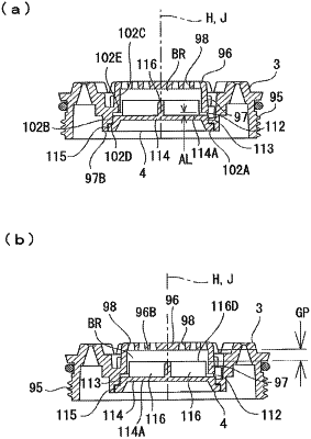
1. An air bubble-liquid mixture generating unit arranged on a shower nozzle, the shower nozzle including:
a shower nozzle plate;
a shower cylindrical portion, which has one cylinder end closed by the shower nozzle plate, is formed to protrude to an outflow passage side, and defines an air bubble mixing space into which a liquid having flowed out through the outflow passage side is caused to flow from another cylinder end of the shower cylindrical portion; and
a plurality of air bubble jetting holes formed in the shower nozzle plate so as to be opened into the air bubble mixing space, and configured to cause an air bubble-liquid mixture to jet out of the air bubble mixing space;
the air bubble-liquid mixture generating unit configured to generate the air bubble-liquid mixture by mixing the air into the liquid;
the air bubble-liquid mixture generating unit further comprising:
a flow-adjustment piece arranged in the air bubble liquid mixture air bubble mixing space in the shower cylindrical portion;
a plurality of air introduction passages formed in the shower nozzle, and configured to cause the air to flow into the air bubble mixing space therethrough;
wherein the flow-adjustment piece including
a flow-adjustment nozzle disk arranged in the air bubble mixing space at a distance from the shower nozzle plate, and fixed to the shower cylindrical portion so as to close the another cylinder end of the shower cylindrical portion;
a plurality of flow-adjustment-piece plates formed on the flow-adjustment nozzle disk arranged at equal intervals in the circumferential direction of the flow-adjustment nozzle disk and arranged in the air bubble mixing space between the shower nozzle plate and the flow-adjustment nozzle disk; and
a plurality of liquid throttle holes formed in a portion of the flow-adjustment nozzle disk between the flow-adjustment-piece plates, and configured to cause the liquid having flowed out through the outflow passage to jet into the air bubble mixing space therethrough;
wherein the flow-adjustment-piece plates have a pair of flow-adjustment flat surfaces and a flow inclined surface, have a plate thickness in the circumferential direction of the flow-adjustment nozzle disk, are formed to protrude from the flow-adjustment nozzle disk to the shower nozzle plate having a plate width, and are arranged with a mixing gap between the shower nozzle plate and a protruding end of the flow-adjustment-piece plates,
wherein the flow-adjustment-piece plates are arranged to extend from a plate center line of the flow-adjustment nozzle disk toward the outer circumferential side of the flow-adjustment nozzle disk with a plate length;
wherein each of the flow-adjustment flat surfaces is formed in a rectangular shape parallel to the flow-adjustment nozzle disk in the circumferential direction with a plate thickness separated from each other;
wherein the flow inclined surface is formed in an inclined manner while extending from the protruding end of each of the flow-adjustment piece plates toward one of the flow-adjustment flat surfaces and the flow-adjustment nozzle disk;
wherein each of the liquid throttle holes is arranged at intervals in the circumferential direction of the flow-adjustment nozzle disk such that the hole center line of each of the liquid throttle holes is parallel to the plate center line of the flow-adjustment nozzle disk;
wherein each of the liquid throttle holes (1) penetrates the flow-adjustment nozzle disk in the direction of the center line of the plate of the flow-adjustment nozzles disk and (2) is opened on the front surface and the back surface of the plate of the flow-adjustment nozzle disk;
wherein each of the liquid holes is formed in a conical hole gradually reducing in diameter from the rear surface of the flow-adjustment nozzle disk towards the front surface of the disk in the direction of the center line of the flow-adjustment nozzle disk, and is opened in the air bubble mixing space between the shower nozzle plate and the flow-adjustment nozzle disk;
wherein the air introduction passages are opened in the shower nozzle and each of the air introduction passages is equally spaced in the circumferential direction of the shower cylindrical portion; and
wherein the air introduction passages are formed to pass through the shower cylindrical portion between the protruding end of each of the flow-adjustment-piece plates and the flow-adjustment nozzle disk in a direction orthogonal to a cylinder center of the shower cylindrical portion, and are opened into the air bubble mixing space.
|