| CPC B01F 25/51 (2022.01) [B01F 25/2122 (2022.01); B01F 25/31113 (2022.01); B01F 25/53 (2022.01); B01F 25/54 (2022.01); B01F 35/1452 (2022.01); B08B 9/0936 (2013.01); B01F 2101/15 (2022.01); B01F 2215/044 (2013.01); C12C 11/00 (2013.01)] | 18 Claims |

|
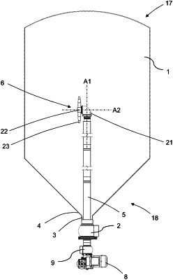
1. A fluid tank system comprising:
a vertically upright tank that includes a top part and a bottom part enclosing an interior, the bottom part of the tank being positioned vertically below the top part of the tank, the bottom part of the tank including a bottom provided with an opening,
a fluid duct connected to the tank for draining fluid from the interior of the tank or for supplying fluid to the interior of the tank, the fluid duct being positioned vertically below the bottom of the tank and in fluid communication with the interior of the tank by way of the opening at the bottom of the tank;
a fluid inlet pipe that possesses an inner surface and oppositely disposed first and second ends, the fluid inlet pipe passing through the fluid duct so that the first end of the fluid inlet pipe is positioned in the interior of the tank and the second end of the fluid inlet pipe is positioned vertically below the fluid duct to receive the fluid to be supplied to the interior of the tank, the fluid inlet pipe extending continuously from the first end to the second end;
a rotary fluid ejector positioned adjacent the first end of the fluid inlet pipe and in fluid communication with the fluid inlet pipe so that fluid introduced into the second end of the fluid inlet pipe flows along the fluid inlet pipe to the first end of the fluid inlet pipe and is introduced to the rotary fluid ejector, the rotary fluid ejector including at least one ejection nozzle configured to eject the fluid flowing along the fluid inlet pipe into the tank;
a rotatable rotary drive shaft extending at least partly inside the fluid inlet pipe, the rotary drive shaft possessing an axially extending outer surface, the inner surface of the fluid inlet pipe facing the outer surface of the rotary drive shaft and being spaced from the outer surface of the rotary drive shaft so that the fluid introduced into the second end of the fluid inlet pipe flows along the fluid inlet pipe toward the first end of the fluid inlet pipe and contacts both the inner surface of the fluid inlet pipe and the outer surface of the rotary drive shaft;
the rotatable rotary drive shaft being rotatably connected to the rotary fluid ejector so that rotation of the rotary drive shaft results in rotation of the at least one ejection nozzle of the rotary fluid ejector; and
the rotary drive shaft possessing an end configured to be connected to a power source to rotate the rotary drive shaft and thereby result in rotation of the at least one ejection nozzle so that the at least one ejection nozzle ejects the fluid into the tank while the at least one ejection nozzle is rotating, the end of the rotary drive shaft being positioned vertically below the fluid duct.
|