| CPC B01D 33/073 (2013.01) [B01D 33/067 (2013.01); B01D 33/64 (2013.01); B01D 33/82 (2013.01); D21C 9/06 (2013.01)] | 10 Claims |

|
1. A rotary pulp filter drum assembly comprising:
a fixed casing (12);
a rotatable drum (10) disposed within the fixed casing (12), the rotatable drum comprising:
a cylindrical water permeable pulp-supporting shell (14),
a rotating hollow shaft (18),
a collecting channel (22) disposed within the cylindrical water permeable pulp-supporting shell (14) for receiving liquid draining through the cylindrical water permeable pulp-supporting shell (14), and
a plurality of radial drain pipes (16), each of the plurality of radial drain pipes having an inlet in fluid communication with the collecting channel (22) and a radially inner outlet (24) for delivering liquid drainage to an interior of the rotating hollow shaft (18); and
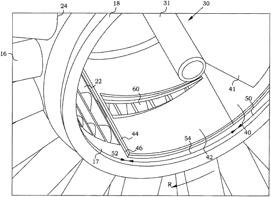
a non-rotating valve arrangement (30) disposed within the rotating hollow shaft (18) and the fixed casing (12), the non-rotating valve arrangement capable of controlling liquid drainage flow through the plurality of radial drain pipes, the non-rotating valve arrangement comprising:
a sealing plate for sealing off a hollow part (37) of the rotating hollow shaft (18) from the radially inner outlet (24) of each of the plurality of radial drain pipes (16) when the radially inner outlet (24) is situated within a sealed zone (50) during rotation of the rotatable drum (10) in a rotation direction R,
a valve plate (42) having an opening (60) that is capable of receiving the liquid drainage flow from each of the plurality of radial drain pipes (16) when each respective radially inner outlet (24) is situated within a transition zone (54) during rotation of the rotatable drum (10) in the rotation direction R, and
a valve shaft (31) longitudinally extending through the rotating hollow shaft (18) and supporting the sealing plate (40) and the valve plate (42);
wherein the non-rotating valve arrangement is arranged to gradually open the opening when the rotatable drum rotates in the rotation direction R; and
wherein, rotation of the rotatable drum in the rotation direction R moves the radially inner outlet (24) of each of the plurality of radial drain pipes about the non-rotating valve arrangement, successively exposing the radially inner outlet of each of the plurality of radial drain pipes to the sealed zone where no liquid drainage flow takes place, the transition zone where some liquid drainage flow takes place, and an open zone (52) where maximum liquid drainage flow takes place, the open zone being between the transition zone the sealed zone.
|