| CPC A61B 8/12 (2013.01) [A61B 8/085 (2013.01); A61B 8/4254 (2013.01); A61B 8/4444 (2013.01); A61B 8/461 (2013.01); A61B 2017/3413 (2013.01); A61B 2034/107 (2016.02); A61B 2090/378 (2016.02)] | 9 Claims |

|
1. A puncture needle positioning system, comprising:
an ultrasound unit (1), including a first probe (11) for providing an ultrasound image of a lesion, wherein a plurality of first positioning devices (4) for providing coordinate information of the first probe (11) are provided on the first probe (11);
a puncture needle unit (2), including a puncture needle, wherein a plurality of second positioning devices (5) for providing coordinate information of the puncture needle are provided on the puncture needle; and
a processing and display unit (3), communicatively connected with the ultrasound unit (1), each of the first positioning devices (4), and each of the second positioning devices (5) respectively;
wherein the ultrasound image of the lesion provided by the first probe (11) is displayed in a virtual coordinate system by the processing and display unit (3);
wherein the coordinate information of the first probe (11) when the first probe (11) is acquiring the ultrasound image of the lesion is sent to the processing and display unit (3);
wherein the processing and display unit (3) determines a planned path (L1) in the virtual coordinate system;
wherein the processing and display unit (3) obtains the coordinate information of the puncture needle provided by each of the second positioning device (5), and displays an axis (L2) of a virtual puncture needle that corresponds to the puncture needle, and a vertex (C2) of the virtual puncture needle in the virtual coordinate system;
wherein the processing and display unit (3), in the virtual coordinate system, compares the axis (L2) of the virtual puncture needle with the planned path (L1) to see if they are coincident;
wherein the processing and display unit (3) further includes a processor; a display; and a plurality of memory units;
wherein the plurality of memory units includes a first memory unit for storing the ultrasound image of the lesion, a second memory unit for storing the coordinate information of the first probe (11), a third memory unit for converting coordinate information of the ultrasound image to an axis of the first probe (11), a fourth memory unit for storing the coordinate information provided by the second positioning devices (5);
wherein the processor is electrically connected to the display and the memory units, and is in data communication with the first probe, the first positioning devices, and the second positioning devices;
wherein the processor receives data representing the ultrasound image of the lesion from the first probe, and data representing the coordinate information of the first probe from the first positioning devices when the first probe is acquiring the ultrasound image of the lesion, and stores the data representing the ultrasound image and the data representing the coordinate information in corresponding memory units, and sends the data representing the ultrasound image and the data representing the coordinate information to the display;
wherein the display receives the data representing the ultrasound image and the data representing the coordinate information from the processor the processor and transforms the data representing the ultrasound image and the data representing the coordinate information into light signals representing the ultrasound image of the lesion and the first probe in the virtual coordinate system;
wherein the processor determines the planned path (L1) in the virtual coordinate system;
wherein the processor receives data representing the coordinate information of the second positioning devices from the second positioning devices and stores the data representing the coordinate information of the second positioning devices in the fourth memory unit;
wherein the processor determines the axis of the first probe (11) based on the data stored in the first memory unit, the second memory unit, and the third memory unit;
wherein the processor compares the coordinate information of the axis (L2) of the virtual puncture needle and the axis of the first probe (11), and sends a signal presenting a judgment of coincidence to the display when the processor finds that the axis of the first probe (11), and the axis (L2) of the virtual puncture needle coincide;
wherein the display emits green light when the display receives the signal presenting the judgment of coincidence from the processor;
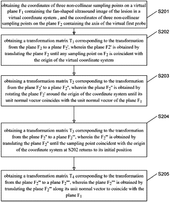
wherein the planned path (L1) is determined by obtaining the position of a projection of the axis of the first probe (11) onto the plane containing the ultrasound image of the lesion through a planar matrix conversion;
wherein the ultrasound image of the lesion is fan-shaped, the virtual coordinate system takes the apex (C1) of the fan-shaped ultrasound image of the lesion as its origin, and the planar matrix conversion is performed according to a transformation formula I to obtain coordinate information of the projection of the axis of the first probe (11) onto the plane containing the ultrasound image of the lesion,
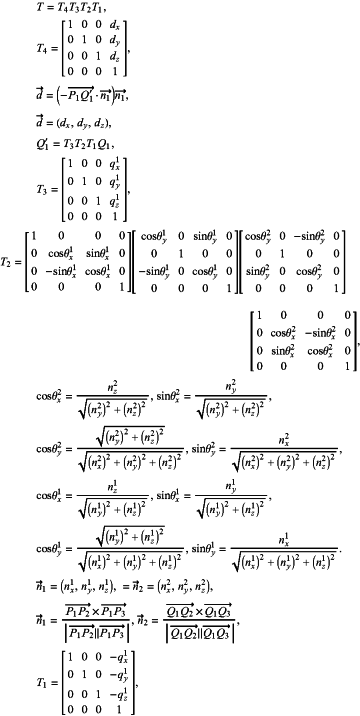
the transformation formula I is given by:
(x′,y′,z′,1)=T(x,y,z,1)T,
wherein (x′, y′, z′, 1) represents the coordinate information of a point on the axis of the first probe after the transformation, (x′, y′, z′, 1)T represents the coordinate information of the point before the transformation,
 P1, P2, P3 are three non-collinear sampling points on the plane F1 containing the ultrasound image of the lesion, and Q1, Q2, Q3 are three non-collinear points on the plane F2 containing the axis of a virtual first probe, P1(px1,py1,pz1), P2(px2,py2,pz2), P3(px3,py3,pz3), Q1(qx1,qy1,qz1), Q2(qx2,qy2,qz2), Q3(qx3,qy3,qz3) are the coordinates of P1, P2, P3, Q1, Q2, and Q3, the virtual first probe is at least partially determined by the first positioning devices (4) on the first probe (11),
n1 is a unit normal vector of the plane F1 containing the ultrasound image of the lesion, and n2 is a unit normal vector of the plane F2,
dx represents a component of the vector −P1Q1 in the equation d=(−P1Q1·n1)n1 in an x-direction, dv represents a component of the vector −P1Q1 in a v-direction, dz represents a component of the vector −P1Q1 in a z-direction.
|