| CPC A01K 87/08 (2013.01) [A01K 87/008 (2022.02)] | 13 Claims |

|
1. A device for use with a fishing rod, comprising:
a tube having a proximal end and a distal end and defining a longitudinal plane between them;
a partial neck disposed along the tube and situated substantially perpendicular to the longitudinal plane of the tube;
a receptacle hole extending from the proximal end and into the tube;
a tang situated at the distal end of the tube, the tang providing a body having flat opposed sides and extending outwardly from substantially the center of the distal end and disposed with a tang hole between the flat opposed sides and within the body;
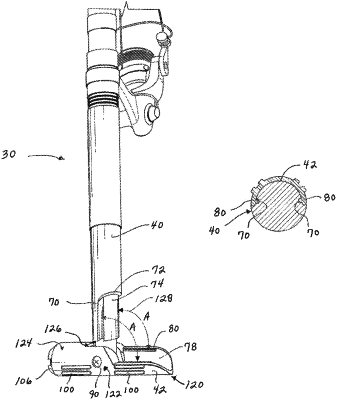
a first surface situated along the tube between the partial neck and the distal end, the first surface forming a convex surface and having a first receiving slot and a second receiving slot each located on opposite sides of the convex surface at a radius of 180 degrees or less from one another, each of the first receiving slot and the second receiving slot providing an interior recessed curved surface and extending parallel to the longitudinal plane from the partial neck to the distal end;
a foot defining an engagement end and a butt end and defining a second longitudinal plane between them;
the engagement end defining an interior surface and an exterior surface, the interior surface forming a concave surface and having a first exterior ridge and a second exterior ridge each located on opposite sides of the concave surface at substantially a radius of 180 degrees or less from one another, each of the first exterior ridge and the second exterior ridge extending parallel to the second longitudinal plane;
the first exterior ridge engaging with the first receiving slot and being received within the interior recessed curved surface of the first receiving slot and the second exterior ridge engaging with the second receiving slot and being received within the interior recessed curved surface of the second receiving slot to releaseably retain the interior surface of the engagement end of the foot to the first surface of the tube;
opposed holes situated between the interior surface and the exterior surface;
the flat opposed sides of the body of the tang inserted into the engagement end of the foot and within the interior surface with the tang hole being aligned between the opposed holes with a screw inserted through the entirety of one of the opposed holes, the tang hole, and the other opposed hole to secure the tube to the foot and define a pivot point;
the foot rotatable about the pivot point when the first exterior ridge and the second exterior ridge are disengaged from both the first receiving slot and the second receiving slot to release the engagement end of the foot from the tube.
|