| CPC H02P 7/04 (2016.02) [E05F 15/60 (2015.01); H02P 7/29 (2013.01); H03K 3/0377 (2013.01); H03K 17/6871 (2013.01); B60J 5/10 (2013.01); B60R 16/033 (2013.01); E05Y 2201/434 (2013.01); E05Y 2900/548 (2013.01); H03K 2217/0063 (2013.01); H03K 2217/0072 (2013.01); H03K 2217/0081 (2013.01)] | 20 Claims |

|
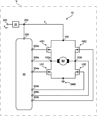
1. A driver circuit, comprising:
a power supply pin configured to receive a power supply voltage;
a set of control pins configured to provide a set of respective control signals for controlling a switching activity of a set of respective switches of an h-bridge circuit, wherein the set of respective switches comprises a pair of high-side switches and a pair of low-side switches;
sensing circuitry coupled to the power supply pin and configured to generate a detection signal indicative of the power supply voltage exceeding a threshold value; and
control circuitry coupled to the set of control pins and sensitive to the detection signal, the control circuitry disabled in an inactive operation state and enabled in an active operation state, the control circuitry, in response to the detection signal being indicative of the power supply voltage exceeding the threshold value, being configured to:
switch to the active operation state in response to the control circuitry being in the inactive operation state, and
generate the control signals to activate the pair of low-side switches and de-activate the pair of high-side switches.
|