| CPC F28F 9/0219 (2013.01) [F28D 7/0041 (2013.01); F28F 9/005 (2013.01); F28F 9/013 (2013.01); F28F 9/0202 (2013.01); F28F 21/00 (2013.01); F28F 9/0212 (2013.01); F28F 9/0224 (2013.01); F28F 9/0226 (2013.01); F28F 9/0231 (2013.01); F28F 2220/00 (2013.01); F28F 2230/00 (2013.01); F28F 2265/26 (2013.01)] | 18 Claims |

|
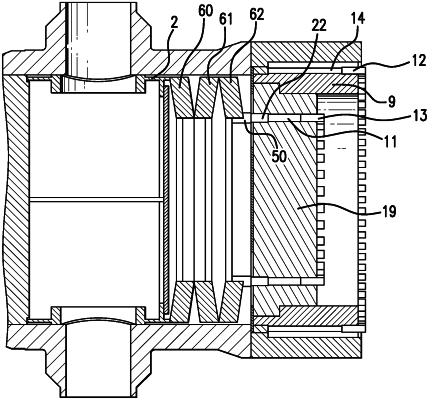
13. A closure assembly configured to removably secure to an open channel end of an interior chamber of a heat exchanger assembly, comprising:
a cylindrical shaped lock ring member defining a cylindrical outer surface portion and a cylindrical shaped interior portion wherein the cylindrical outer surface portion is provided with a plurality of spaced-apart lock ring hub sections configured to interdigitate with corresponding channel hub sections formed on a cylindrical inner surface portion of the heat exchanger assembly;
a cylindrical shaped cover member secured concentric with the cylindrical shaped interior portion of the cylindrical shaped lock ring member;
a diaphragm configured to be positioned adjacent to the lock ring and cylindrical shaped cover member;
a plurality of adjustable outer elongate lock ring compression members removably securable in the cylindrical shaped lock ring member, each adjustable outer elongate lock ring compression member passing through a respective hole coaxially formed with a longitudinal axis in the cylindrical shaped lock ring member so as to transmit a force to a first compression ring, which transmits the force to a rim portion of the diaphragm;
a diaphragm gasket compressed against the diaphragm such that the diaphragm is positioned intermediate the diaphragm gasket and the first compression ring member through adjustment of the adjustable outer elongate lock ring compression members when the cylindrical shaped lock ring member is removably secured to the interior chamber of the tubular heat exchanger assembly; and
a plurality of inner adjustable elongate cover compression members removably securable in the cylindrical shaped cover member, each adjustable inner elongate cover compression member passing through a respective hole coaxially formed with a longitudinal axis in the cylindrical shaped cover member so as to transmit a force to a second compression ring, which transmits the force to a portion of the diaphragm causing a portion of the diaphragm to deflect distal from the cylindrical shaped cover member and towards the interior chamber of the heat exchanger assembly when the closure assembly is removably secured to the open end of the interior chamber of the heat exchanger assembly.
|
|
18. A process for assembling a tube heat exchanger assembly comprising:
providing an elongated heat exchanger enclosure having an interior chamber and defining a longitudinal axis and having an open cylindrical channel end;
providing a closure assembly having a locking assembly configured to secure to the open cylindrical channel end of the elongated heat exchanger enclosure;
inserting the locking assembly of the closure assembly into the open cylindrical channel end axially along the longitudinal axis of the interior chamber of the heat exchanger such that load bearing surfaces of each of the closure assembly and an interior wall of the elongated heat exchanger enclosure do not contact one another;
turning the closure assembly about the longitudinal axis of the elongated heat exchanger enclosure less than 360 degrees relative to the elongated heat exchanger enclosure to cause the locking assembly to removably secure to a cooperating locking assembly provided on the interior wall of the elongated heat exchanger enclosure to cause the load bearing surfaces to contact one another such that a load is transferred between the closure assembly and the elongated heat exchanger: and
wherein turning the closure assembly includes causing spaced-apart lock ring hub sections of the closure assembly to interdigitate with corresponding channel hub sections of the cooperating locking assembly of the elongated heat exchanger enclosure.
|