| CPC F16L 3/1066 (2013.01) [A47F 5/00 (2013.01); A47F 5/0892 (2013.01); E04B 9/006 (2013.01); E04B 9/183 (2013.01); F16L 3/006 (2013.01); F16L 3/20 (2013.01); F16M 13/027 (2013.01); F24F 13/0254 (2013.01)] | 13 Claims |

|
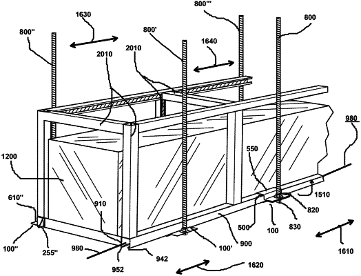
1. A structural framework comprising:
(a) a first support beam, the first beam having first and second flanges, and an interior, the first support beam having a first longitudinal centerline;
(b) a first support bracket connectable to the first support beam, the first support bracket comprising:
(i) a first flange of the first support bracket,
(ii) a second flange of the first support bracket, the first flange of the first support bracket meeting the second flange of the first support bracket at an apex and forming an angle with the second flange of the first support bracket,
(iii) a support section connected to the first flange of the first support bracket, wherein the first support bracket has locked and unlocked states relative to the first support beam, and the first support bracket changes from an unlocked state to a locked state relative to the first support beam by rotation in a first rotational direction about an axis which is generally parallel to the first longitudinal axis and creating a locking force between the first support bracket and the first support beam, and the first support bracket changes from a locked state to an unlocked state relative to the first support beam by rotation in a second rotational direction about the axis which is generally parallel to the first longitudinal axis; and
(iv) a first clamping section releasably connectable to the first support bracket and when connected to the first support bracket maintaining the first support bracket in the locked state relative to the first support beam by squeezing the first support beam between the first support bracket and the first clamping section.
|