| CPC F02C 7/047 (2013.01) [F01D 25/08 (2013.01); F05D 2220/36 (2013.01); F05D 2260/20 (2013.01)] | 20 Claims |

|
1. A turbofan engine defining an axial direction and a radial direction, the turbofan engine comprising:
a fan;
a turbomachine operably coupled to the fan for driving the fan, wherein the turbomachine, the fan, or both include an engine component;
a heat source; and
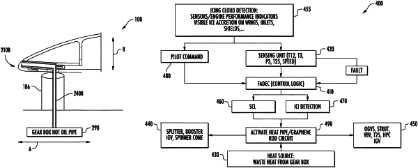
a heat transfer system configured to reduce ice buildup or ice formation in the engine component, the heat transfer system in communication with the heat source, the heat transfer system comprising:
a first heat transfer component having a hot interface and a cold interface, wherein the hot interface is in thermal communication with the heat source; and
a second heat transfer component that extends from the first heat transfer component to or through the engine component, wherein the first heat transfer component comprises one of a heat pipe or a graphene rod, and wherein the second heat transfer component comprises the other of the heat pipe or the graphene rod, wherein the first heat transfer component and the second heat transfer component are fluidly coupled together and configured to recirculate a phase change material therethrough, wherein the phase change material is in an at least partial vapor phase at the hot interface and condenses into a liquid phase at the cold interface, wherein the phase change material releases latent heat of the phase change material to heat the engine component.
|