US 11,970,008 B2
Tank and liquid droplet jetting apparatus connected to the same
Akinori Igarashi, Kasugai (JP)
Assigned to BROTHER KOGYO KABUSHIKI KAISHA, Nagoya (JP)
Filed by BROTHER KOGYO KABUSHIKI KAISHA, Nagoya (JP)
Filed on Sep. 2, 2022, as Appl. No. 17/929,363.
Application 17/929,363 is a continuation of application No. 17/175,902, filed on Feb. 15, 2021, granted, now 11,433,682.
Application 17/175,902 is a continuation of application No. 16/895,215, filed on Jun. 8, 2020, granted, now 10,919,306, issued on Feb. 16, 2021.
Application 16/895,215 is a continuation of application No. 16/376,384, filed on Apr. 5, 2019, granted, now 10,675,880, issued on Jun. 9, 2020.
Application 16/376,384 is a continuation of application No. 16/105,070, filed on Aug. 20, 2018, granted, now 10,252,537, issued on Apr. 9, 2019.
Application 16/105,070 is a continuation of application No. 15/726,787, filed on Oct. 6, 2017, granted, now 10,052,879, issued on Aug. 21, 2018.
Application 15/726,787 is a continuation of application No. 15/276,049, filed on Sep. 26, 2016, granted, now 9,782,975, issued on Oct. 10, 2017.
Application 15/276,049 is a continuation of application No. 14/735,864, filed on Jun. 10, 2015, granted, now 9,457,581, issued on Oct. 4, 2016.
Claims priority of application No. 2014-121856 (JP), filed on Jun. 12, 2014.
Prior Publication US 2023/0132769 A1, May 4, 2023
Int. Cl. B41J 2/175 (2006.01)
CPC B41J 2/17553 (2013.01) [B41J 2/175 (2013.01); B41J 2/17513 (2013.01); B41J 2/1752 (2013.01); B41J 2/17503 (2013.01)] 10 Claims
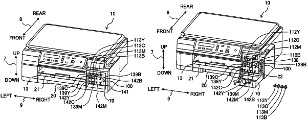
OG exemplary drawing
 
1. A tank configured to store a liquid which is to be supplied to a liquid consuming apparatus, the tank comprising:
a wall defining a liquid storage chamber configured to store the liquid, the wall including:
an upper wall extending in a front-rear direction;
a front wall extending in an upper-lower direction, the front wall being located below the upper wall in the upper-lower direction;
a first lower wall extending rearward from a lower end of the front wall; and
a second lower wall extending rearward from a position away rearward from the front wall, the second wall being located below the first lower wall in the upper-lower direction;
an inlet which penetrates through the upper wall or the front wall and via which the liquid is flowed into the liquid storage chamber;
an outlet via which the liquid is flowed out; and
a liquid lead-out channel configured to flow the liquid flowed out from the outlet to the liquid consuming apparatus,
wherein the outlet is located between the first lower wall and the second lower wall in the upper-lower direction.